HP LH4r HP Netserver LH 3 30/FC Installation Guide - Page 66
Unpack the HP Model 30/FC High Availability Disk Array
 |
View all HP LH4r manuals
Add to My Manuals
Save this manual to your list of manuals |
Page 66 highlights
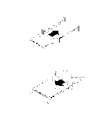
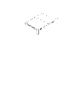
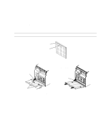
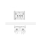
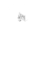
The HP Model 30/FC High Availability Disk Array is rated to draw approximately 5amps at 230VAC steady state current for normal operation. However, when powered on, the disk array draws a heavy in-rush (surge) current (up to 115 amps for 10 to 12 ms) that could trip standard industrial circuit breakers. Hewlett-Packard strongly recommends installing magnetic-type circuit breakers capable of handling large in-rush currents for short durations (10 to 12 milliseconds), but rated adequately for steady state currents. For European installations, Hewlett-Packard strongly recommends installing 20A circuit breakers, Type C or Type D per IEC 898, or Type K per IEC 947-2. All electrical wiring to the service point (plug) for the disk array should be sized adequately to carry the in-rush and steady state currents shown above. 2. Unpack the HP Model 30/FC High Availability Disk Array The HP Model 30/FC High Availability Disk Array must be installed into an HP E3662A or E3662B 2.0m high, 19-inch wide, 220VAC, EIA cabinet (also called a rack) at the installation site. The disk modules for the disk array are packaged in boxes separate from the disk array chassis. Each box containing disk modules has a label imprinted with the chassis number of the disk array into which the disk modules should be installed. The disk modules are shipped with the disk array and banded to the pallet. Boxes of cables and accessories are shipped separately. a. Move the disk array, disk modules, and boxes containing the cables and accessories to the cabinet where the equipment will be installed. b. Cut the plastic bands around the shipping carton and pallet. WARNING Wear protective glasses while cutting the plastic strapping bands. They are under tension; when cut, they can spring back and cause serious eye injury. c. Remove the shipping carton(s) containing the disk modules from the top of the disk array's shipping carton. d. Open the disk array's shipping carton by cutting the tape over the seams. e. Lift the shipping carton off the disk array. f. Remove all foam strips from around the disk array. WARNING Do not lift the disk array chassis by the fan pack handle at the back of the disk array. Doing so can damage the disk array. The disk array is very heavy. Use extreme care when moving or lifting it. At least two persons are needed to lift and safely install a disk array into a cabinet. g. Remove the cardboard braces from the ends of the disk array. Keeping your hands under the bottom of the unit, lift the disk array off the pallet. Place the unit on a suitably sturdy, anti-static work surface. h. Remove the protective covering from the disk array. 15
-
 1
1 -
2
-
3
-
4
-
5
-
6
-
7
-
8
-
9
-
10
-
11
-
12
-
13
-
14
-
15
-
16
-
17
-
18
-
19
-
20
-
21
-
22
-
23
-
24
-
25
-
26
-
27
-
28
-
29
-
30
-
31
-
32
-
33
-
34
-
35
-
36
-
37
-
38
-
39
-
40
-
41
-
42
-
43
-
44
-
45
-
46
-
47
-
48
-
49
-
50
-
51
-
52
-
53
-
54
-
55
-
56
-
57
-
58
-
59
-
60
-
 61
61 -
 62
62 -
 63
63 -
 64
64 -
 65
65 -
 66
66 -
 67
67 -
 68
68 -
 69
69 -
 70
70 -
 71
71 -
72
-
73
-
74
-
75
-
76
-
77
-
78
-
79
-
80
-
81
-
82
-
83
-
84
-
85
-
86
-
87
-
88
-
89
-
90
 |
 |
