HP LH4r HP Netserver LH 3 30/FC Installation Guide - Page 73
Hewlett-Packard Model 30/FC High Availability Disk Array, Service Manual
 |
View all HP LH4r manuals
Add to My Manuals
Save this manual to your list of manuals |
Page 73 highlights
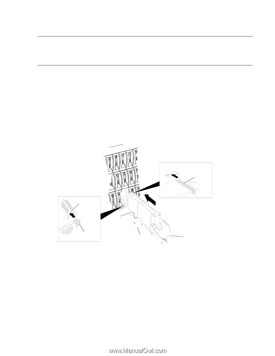
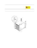
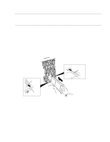
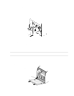
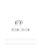
e. Unpack and install the disk modules. CAUTION Handle disk modules very carefully as they can be damaged easily by shock and vibration. Strap the ESD wrist strap to your wrist and ground it to the disk array chassis (or suitable ground). Place the disk module on an ESD conductive sheet when it is removed from its carton. Use ESD kit P/N 5182-4119 (supplied with each disk array). Make sure each disk module's label, which shows its slot ID (A0, for example), is present. The disk modules must be installed in the slot that matches the slot ID on the label. For the slot ID numbers, refer to the disk array chassis illustrations in chapter 1 of the Hewlett-Packard Model 30/FC High Availability Disk Array Service Manual (A3661-90002). Make sure that all the disk slots contain disk modules or filler panels to ensure proper cooling. - Observe anti-static precautions. - Locate the slot where the disk module is to be installed (see figure 17). - Write the slot number the disk is being installed into on the label affixed to the disk module; for example, A1. - Install the disk module gently but firmly by sliding it into the slot. Rough handling can damage the disk module. Seat the disk module slowly into the connector. Rail slot Guide slot Disk module's guide Disk module's rail ESD wrist strap Figure 17. Installing a disk module 22
-
 1
1 -
2
-
3
-
4
-
5
-
6
-
7
-
8
-
9
-
10
-
11
-
12
-
13
-
14
-
15
-
16
-
17
-
18
-
19
-
20
-
21
-
22
-
23
-
24
-
25
-
26
-
27
-
28
-
29
-
30
-
31
-
32
-
33
-
34
-
35
-
36
-
37
-
38
-
39
-
40
-
41
-
42
-
43
-
44
-
45
-
46
-
47
-
48
-
49
-
50
-
51
-
52
-
53
-
54
-
55
-
56
-
57
-
58
-
59
-
60
-
61
-
62
-
63
-
64
-
65
-
66
-
67
-
 68
68 -
 69
69 -
 70
70 -
 71
71 -
 72
72 -
 73
73 -
 74
74 -
 75
75 -
 76
76 -
 77
77 -
 78
78 -
79
-
80
-
81
-
82
-
83
-
84
-
85
-
86
-
87
-
88
-
89
-
90
 |
 |