HP LH4r HP Netserver LH 3 30/FC Installation Guide - Page 77
Plan the HP FC-AL Hub Connections, How to Make an FC-AL Connection
 |
View all HP LH4r manuals
Add to My Manuals
Save this manual to your list of manuals |
Page 77 highlights
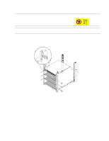
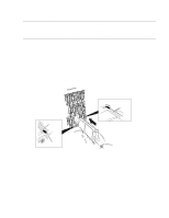
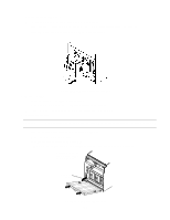
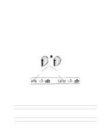
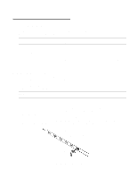
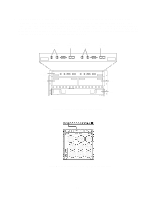
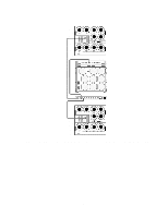
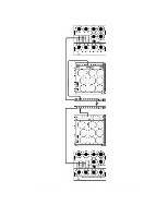
4 - Cluster Cabling and Setup 1. Plan the HP FC-AL Hub Connections The HP NetServers should be powered down when making the FC-AL connections to the FC I/O adapters. Power down the HP NetServers if they are not already powered down. The HP Model 30/FC High Availability Disk Array and the cabinet should still be powered down at this time. CAUTION Incorrect wiring can lead to problems, such as devices left off the loop and inaccessible by the HP NetServer. Follow the guidelines below before starting. a. Review the hardware address of each FC-AL device to be connected to the HP FC-AL hub, and make sure each ID is unique. Duplicate IDs on the loop can cause problems. In addition, each device has its own factory-assigned unique worldwide name. b. Verify that the connections between the HP FC-AL hub port and the disk array or the FC I/O adapter in the HP NetServers are of the same wave type and speed. For example, plan to connect a short-wave port on the HP FC-AL hub to a short-wave port on an FC-AL device. c. Document the planned connections in a cabling map. 2. How to Make an FC-AL Connection To connect a fiber optic cable to an HP FC-AL hub, find any available, appropriate Fibre Channel port on the HP FC-AL hub, remove the FC port cover, and connect the fibre optic cable. No priority or hierarchy is assigned to the connectors on the HP FC-AL hub. The cable connector is keyed to avoid incorrect installation. Short wave cables should be used to connect short-wave ports. A long-wave cable should be used to connect the long-wave ports of cascading long-wave hubs. NOTE Fiber optic cables and connectors are extremely fragile. Avoid twisting or bending the cable to less than a 3 cm radius. If using a single short-wave hub, FC-AL connections can be made to any of the 10 short-wave ports of the HP FC-AL hub. That is, the FC I/O adapters and the disk array can be connected to any ports on the HP FC-AL hub. If using cascading short-wave hubs, connections between HP FC-AL hubs and from the HP FC-AL hub to the FC I/O adapters and the disk array can be made to any of the 10 ports on the HP FC-AL hub. If using a single long-wave hub, FC I/O adapters and the disk array can be connected to Port 1 through Port 9 (the leftmost nine, short-wave ports). Port 10 (the rightmost, long-wave port) should not be used to connect these devices. If using cascading long-wave hubs, the two HP FC-AL hubs should be connected to each other using the long-wave Port 10. Port 1 through Port 9, the short-wave ports, can be used to connect FC I/O adapters and the disk array. Figure 21. Connecting a fiber optic cable to a Fibre Channel connector 26
-
 1
1 -
2
-
3
-
4
-
5
-
6
-
7
-
8
-
9
-
10
-
11
-
12
-
13
-
14
-
15
-
16
-
17
-
18
-
19
-
20
-
21
-
22
-
23
-
24
-
25
-
26
-
27
-
28
-
29
-
30
-
31
-
32
-
33
-
34
-
35
-
36
-
37
-
38
-
39
-
40
-
41
-
42
-
43
-
44
-
45
-
46
-
47
-
48
-
49
-
50
-
51
-
52
-
53
-
54
-
55
-
56
-
57
-
58
-
59
-
60
-
61
-
62
-
63
-
64
-
65
-
66
-
67
-
68
-
69
-
70
-
71
-
 72
72 -
 73
73 -
 74
74 -
 75
75 -
 76
76 -
 77
77 -
 78
78 -
 79
79 -
 80
80 -
 81
81 -
 82
82 -
83
-
84
-
85
-
86
-
87
-
88
-
89
-
90
 |
 |
