HP LH4r HP Netserver LH 3 30/FC Installation Guide - Page 76
Table 2 - Fibre Channel Addresses, To part 3 of the HP NetServer Installation Guide.
 |
View all HP LH4r manuals
Add to My Manuals
Save this manual to your list of manuals |
Page 76 highlights
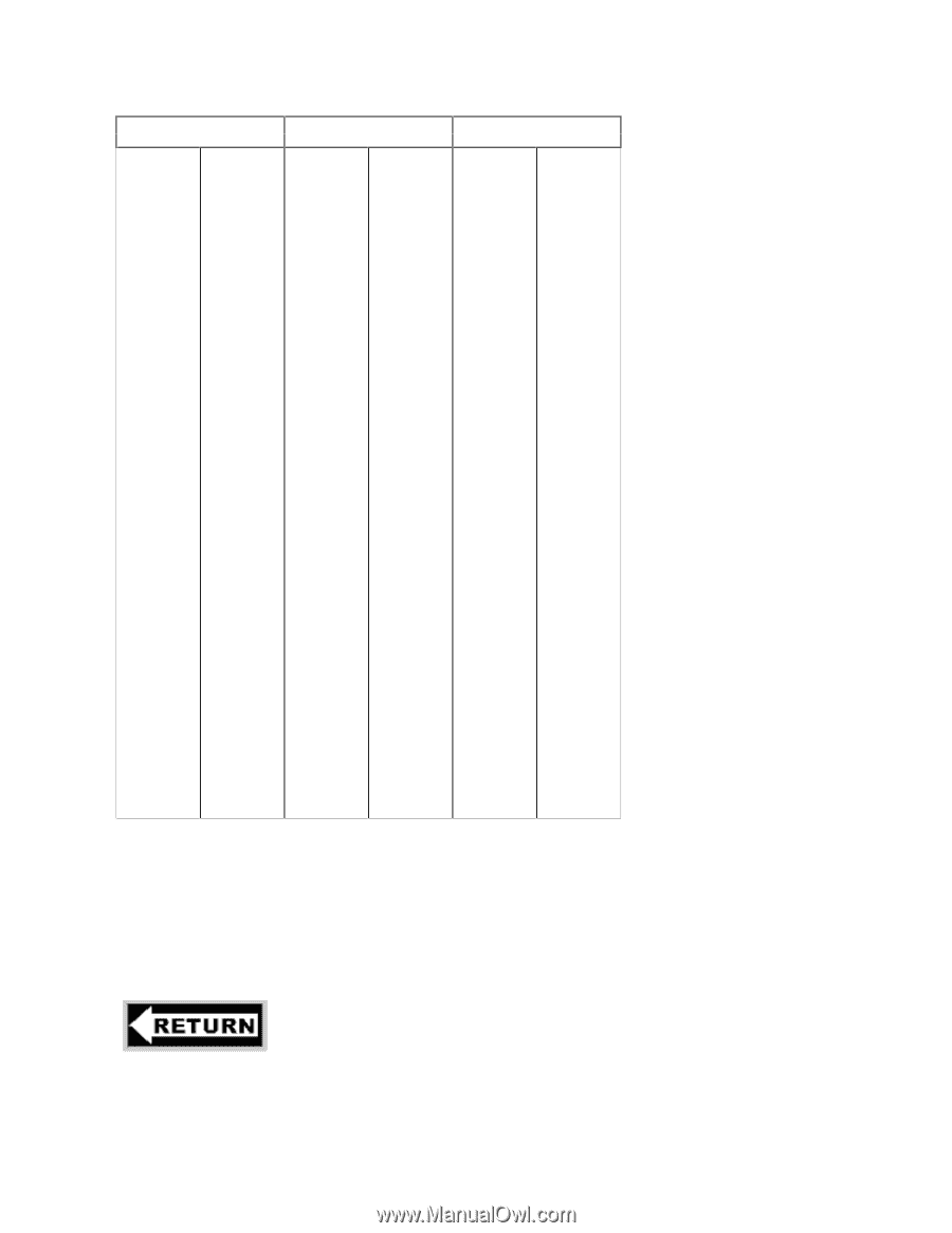
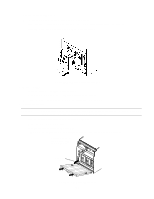
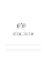
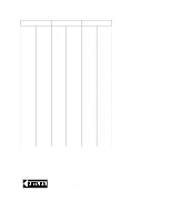
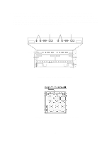
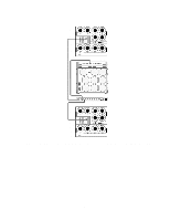
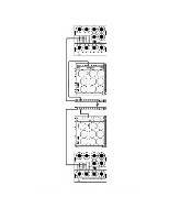
Table 2 - Fibre Channel Addresses FC address (Loop ID) (hexadecimal) (decimal) 00 0 01 1 02 2 03 3 04 4 05 5 06 6 07 7 08 8 09 9 0A 10 0B 11 0C 12 0D 13 0E 14 0F 15 10 16 11 17 12 18 13 19 14 20 15 21 16 22 17 23 18 24 19 25 1A 26 1B 27 1C 28 1D 29 1E 30 1F 31 20 32 21 33 22 34 23 35 24 36 25 37 26 38 27 39 28 40 29 41 2A 42 FC address (Loop ID) (hexadecimal) (decimal) 2B 43 2C 44 2D 45 2E 46 2F 47 30 48 31 49 32 50 33 51 34 52 35 53 36 54 37 55 38 56 39 57 3A 58 3B 59 3C 60 3D 61 3E 62 3F 63 40 64 41 65 42 66 43 67 44 68 45 69 46 70 47 71 48 72 49 73 4A 74 4B 75 4C 76 4D 77 4E 78 4F 79 50 80 51 81 52 82 53 83 54 84 FC address (Loop ID) (hexadecimal) (decimal) 55 85 56 86 57 87 58 88 59 89 5A 90 5B 91 5C 92 5D 93 5E 94 5F 95 60 96 61 97 62 98 63 99 64 100 65 101 66 102 67 103 68 104 69 105 6A 106 6B 107 6C 108 6D 109 6E 110 6F 111 70 112 71 113 72 114 73 115 74 116 75 117 76 118 77 119 78 120 79 121 7A 122 7B 123 7C 124 7D 125 7E 126 To install additional HP Model 30/FC High Availability Disk Arrays into the same cabinet, first verify that 11 EIA units of space are available in the cabinet, then repeat steps 2 through 5. Be sure to set the Fibre Channel address of each SP in each disk array to a unique number. Do not attach Fibre Channel cables or power cords at this time. Also, do not power up the cabinet at this time. To part 3 of the HP NetServer Installation Guide. 25
-
 1
1 -
2
-
3
-
4
-
5
-
6
-
7
-
8
-
9
-
10
-
11
-
12
-
13
-
14
-
15
-
16
-
17
-
18
-
19
-
20
-
21
-
22
-
23
-
24
-
25
-
26
-
27
-
28
-
29
-
30
-
31
-
32
-
33
-
34
-
35
-
36
-
37
-
38
-
39
-
40
-
41
-
42
-
43
-
44
-
45
-
46
-
47
-
48
-
49
-
50
-
51
-
52
-
53
-
54
-
55
-
56
-
57
-
58
-
59
-
60
-
61
-
62
-
63
-
64
-
65
-
66
-
67
-
68
-
69
-
70
-
 71
71 -
 72
72 -
 73
73 -
 74
74 -
 75
75 -
 76
76 -
 77
77 -
 78
78 -
 79
79 -
 80
80 -
 81
81 -
82
-
83
-
84
-
85
-
86
-
87
-
88
-
89
-
90
 |
 |