HP LH4r HP Netserver LH 3 30/FC Installation Guide - Page 67
Prepare the Cabinet
 |
View all HP LH4r manuals
Add to My Manuals
Save this manual to your list of manuals |
Page 67 highlights
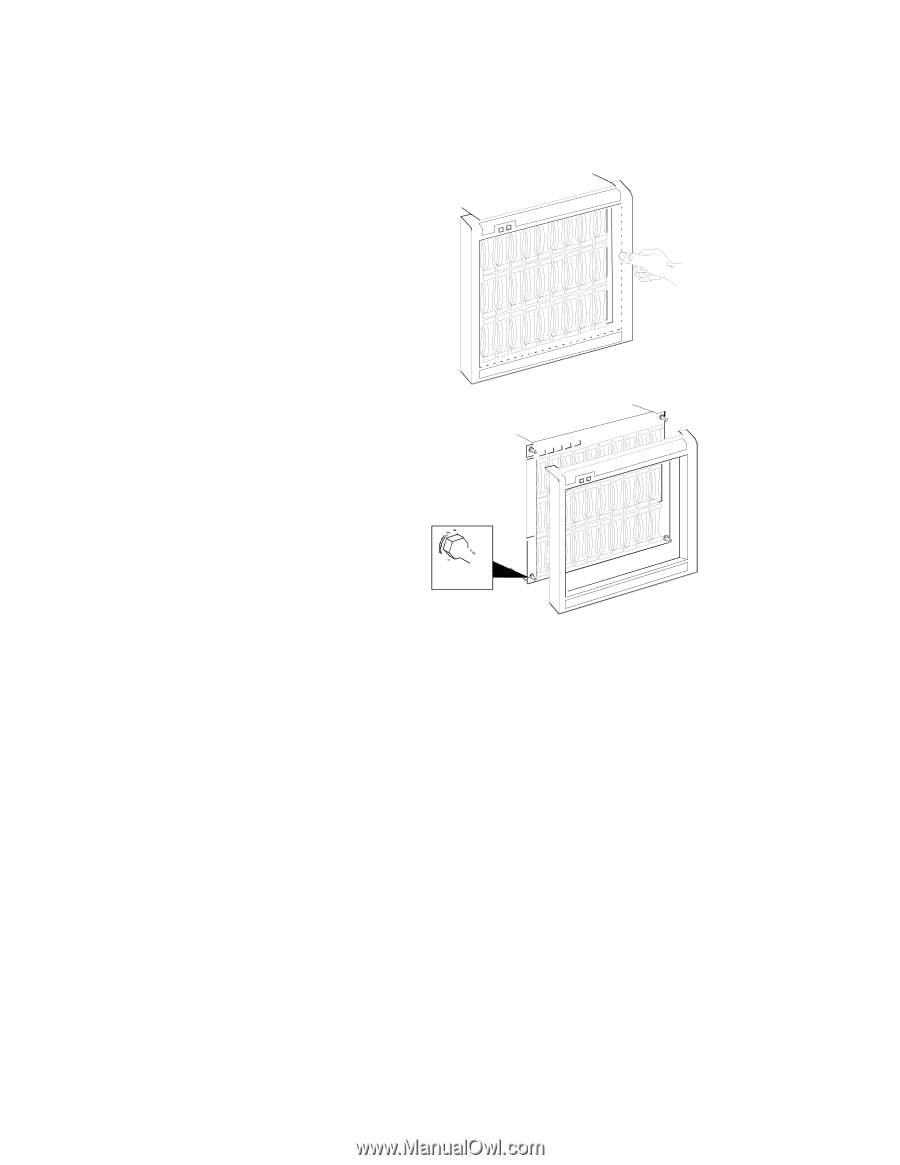
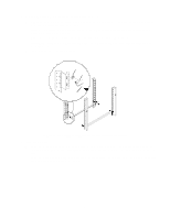
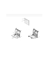
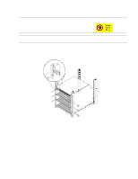
i. Remove the disk array's front bezel by grasping its sides and pulling straight out. If the bezel is difficult to remove, use a small standard screwdriver to carefully loosen the bezel at its four outside corners. To remove front bezel, grasp the sides of the panel and pull straight out. To install front bezel, press panel onto ballstuds. Ballstud Figure 10. Removing the front bezel 3. Prepare the Cabinet The HP Model 30/FC High Availability Disk Array requires 11 EIA units of space in the cabinet. The hardware mounting kit (part number A3661-60006), which is shipped with the disk array, consists of: - 2 rails (part number A3661-00002) - 20 retaining screws (part number 2680-0278) - 16 clip nuts (part number 0590-0804) - 1 custom trim panel (part number A3661-00001) a. Make sure the cabinet is powered down. Refer to the cabinet documentation for more information. b. Remove any trim and open the doors of the cabinet. Refer to the cabinet documentation for more information. 16
-
 1
1 -
2
-
3
-
4
-
5
-
6
-
7
-
8
-
9
-
10
-
11
-
12
-
13
-
14
-
15
-
16
-
17
-
18
-
19
-
20
-
21
-
22
-
23
-
24
-
25
-
26
-
27
-
28
-
29
-
30
-
31
-
32
-
33
-
34
-
35
-
36
-
37
-
38
-
39
-
40
-
41
-
42
-
43
-
44
-
45
-
46
-
47
-
48
-
49
-
50
-
51
-
52
-
53
-
54
-
55
-
56
-
57
-
58
-
59
-
60
-
61
-
 62
62 -
 63
63 -
 64
64 -
 65
65 -
 66
66 -
 67
67 -
 68
68 -
 69
69 -
 70
70 -
 71
71 -
 72
72 -
73
-
74
-
75
-
76
-
77
-
78
-
79
-
80
-
81
-
82
-
83
-
84
-
85
-
86
-
87
-
88
-
89
-
90
 |
 |