HP Pavilion dm4-3000 HP Pavilion dm4 Entertainment PC - Maintenance and Servic - Page 78
Display assembly, spare part information, see the individual removal sub s.
 |
View all HP Pavilion dm4-3000 manuals
Add to My Manuals
Save this manual to your list of manuals |
Page 78 highlights
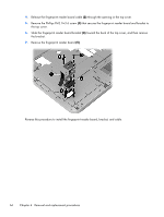
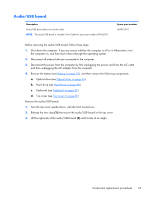
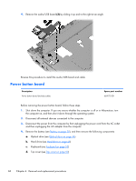
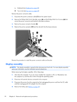
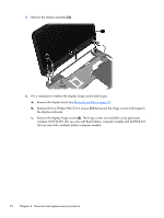
c. Keyboard (see Keyboard on page 57) d. Top cover (see Top cover on page 60) Remove the power connector cable: 1. Disconnect the power connector cable (1) from the system board. 2. Remove the Phillips PM2.5×6.8 shoulder screw (2) and the Phillips PM2.5×4.5 screw (3) that secure the power connector and bracket to the base enclosure. 3. Remove the power connector bracket (4). 4. Remove the power connector (5) from the clip built into the base enclosure. Reverse this procedure to install the power connector cable and bracket. Display assembly NOTE: The display assembly is spared at the subcomponent level only. For more display assembly spare part information, see the individual removal subsections. Before removing the display assembly, follow these steps: 1. Shut down the computer. If you are unsure whether the computer is off or in Hibernation, turn the computer on, and then shut it down through the operating system. 2. Disconnect all external devices connected to the computer. 3. Disconnect the power from the computer by first unplugging the power cord from the AC outlet and then unplugging the AC adapter from the computer. 4. Remove the battery (see Battery on page 39). 70 Chapter 4 Removal and replacement procedures
-
 1
1 -
2
-
3
-
4
-
5
-
6
-
7
-
8
-
9
-
10
-
11
-
12
-
13
-
14
-
15
-
16
-
17
-
18
-
19
-
20
-
21
-
22
-
23
-
24
-
25
-
26
-
27
-
28
-
29
-
30
-
31
-
32
-
33
-
34
-
35
-
36
-
37
-
38
-
39
-
40
-
41
-
42
-
43
-
44
-
45
-
46
-
47
-
48
-
49
-
50
-
51
-
52
-
53
-
54
-
55
-
56
-
57
-
58
-
59
-
60
-
61
-
62
-
63
-
64
-
65
-
66
-
67
-
68
-
69
-
70
-
71
-
72
-
 73
73 -
 74
74 -
 75
75 -
 76
76 -
 77
77 -
 78
78 -
 79
79 -
 80
80 -
 81
81 -
 82
82 -
 83
83 -
84
-
85
-
86
-
87
-
88
-
89
-
90
-
91
-
92
-
93
-
94
-
95
-
96
-
97
-
98
-
99
-
100
-
101
-
102
-
103
-
104
-
105
-
106
-
107
-
108
-
109
-
110
-
111
-
112
-
113
-
114
-
115
-
116
-
117
-
118
-
119
-
120
 |
 |