HP Pavilion dm4-3000 HP Pavilion dm4 Entertainment PC - Maintenance and Servic - Page 84
System board, When replacing the system board
 |
View all HP Pavilion dm4-3000 manuals
Add to My Manuals
Save this manual to your list of manuals |
Page 84 highlights
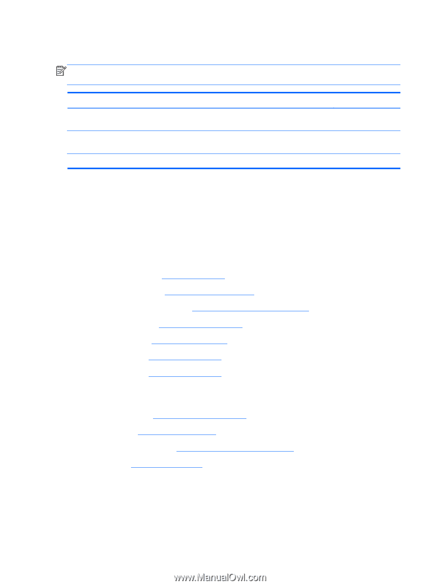
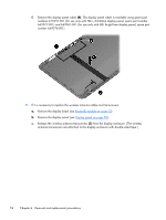
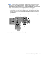
System board NOTE: The system board spare part kit includes replacement thermal material. Replacement thermal material is also available in the Thermal Material Kit, spare part number 669929-001. Description For use only with computer models equipped with the Intel 7570 chipset and a graphics subsystem with discrete memory For use only with computer models equipped with the Intel 6490 chipset and a graphics subsystem with discrete memory For use only with computer models equipped with a graphics subsystem with UMA memory Spare part number 676577-001 669084-001 669085-001 Before removing the system board, follow these steps: 1. Shut down the computer. If you are unsure whether the computer is off or in Hibernation, turn the computer on, and then shut it down through the operating system. 2. Disconnect all external devices connected to the computer. 3. Disconnect the power from the computer by first unplugging the power cord from the AC outlet and then unplugging the AC adapter from the computer. 4. Remove the battery (see Battery on page 39), and then remove the following components: a. WLAN module (see WLAN module on page 41) b. mSATA solid-state drive (see mSATA solid-state drive on page 44) c. Optical drive (see Optical drive on page 46) d. Hard drive (see Hard drive on page 48) e. Keyboard (see Keyboard on page 57) f. Top cover (see Top cover on page 60) When replacing the system board, be sure that the following components are removed from the defective system board and installed on the replacement system board: ● Memory module (see Memory module on page 45) ● RTC battery (see RTC battery on page 51) ● Fan/heat sink assembly (see Fan/heat sink assembly on page 79) ● Processor (see Processor on page 82) Remove the system board: 1. Close the computer. 2. Turn the computer upside down, with the front toward you. 76 Chapter 4 Removal and replacement procedures
-
 1
1 -
2
-
3
-
4
-
5
-
6
-
7
-
8
-
9
-
10
-
11
-
12
-
13
-
14
-
15
-
16
-
17
-
18
-
19
-
20
-
21
-
22
-
23
-
24
-
25
-
26
-
27
-
28
-
29
-
30
-
31
-
32
-
33
-
34
-
35
-
36
-
37
-
38
-
39
-
40
-
41
-
42
-
43
-
44
-
45
-
46
-
47
-
48
-
49
-
50
-
51
-
52
-
53
-
54
-
55
-
56
-
57
-
58
-
59
-
60
-
61
-
62
-
63
-
64
-
65
-
66
-
67
-
68
-
69
-
70
-
71
-
72
-
73
-
74
-
75
-
76
-
77
-
78
-
 79
79 -
 80
80 -
 81
81 -
 82
82 -
 83
83 -
 84
84 -
 85
85 -
 86
86 -
 87
87 -
 88
88 -
 89
89 -
90
-
91
-
92
-
93
-
94
-
95
-
96
-
97
-
98
-
99
-
100
-
101
-
102
-
103
-
104
-
105
-
106
-
107
-
108
-
109
-
110
-
111
-
112
-
113
-
114
-
115
-
116
-
117
-
118
-
119
-
120
 |
 |