HP Pavilion dm4-3000 HP Pavilion dm4 Entertainment PC - Maintenance and Servic - Page 79
Support the display assembly when removing the following screws. Failure
 |
View all HP Pavilion dm4-3000 manuals
Add to My Manuals
Save this manual to your list of manuals |
Page 79 highlights
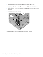
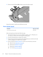
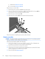
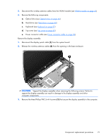
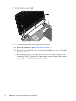
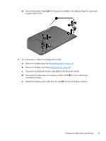
5. Disconnect the wireless antenna cables from the WLAN module (see WLAN module on page 41). 6. Remove the following components: a. Optical drive (see Optical drive on page 46) b. Hard drive (see Hard drive on page 48) c. Keyboard (see Keyboard on page 57) d. Top cover (see Top cover on page 60) e. Power connector cable (see Power connector cable on page 69) Remove the display assembly: 1. Disconnect the display panel cable (1) from the system board. 2. Release the wireless antenna cables (2) from the opening in the base enclosure. CAUTION: Support the display assembly when removing the following screws. Failure to support the display assembly can result in damage to the display assembly and other computer components. 3. Remove the three Phillips PM2.5×4.4 screws (1) that secure the display assembly to the computer. Component replacement procedures 71
-
 1
1 -
2
-
3
-
4
-
5
-
6
-
7
-
8
-
9
-
10
-
11
-
12
-
13
-
14
-
15
-
16
-
17
-
18
-
19
-
20
-
21
-
22
-
23
-
24
-
25
-
26
-
27
-
28
-
29
-
30
-
31
-
32
-
33
-
34
-
35
-
36
-
37
-
38
-
39
-
40
-
41
-
42
-
43
-
44
-
45
-
46
-
47
-
48
-
49
-
50
-
51
-
52
-
53
-
54
-
55
-
56
-
57
-
58
-
59
-
60
-
61
-
62
-
63
-
64
-
65
-
66
-
67
-
68
-
69
-
70
-
71
-
72
-
73
-
 74
74 -
 75
75 -
 76
76 -
 77
77 -
 78
78 -
 79
79 -
 80
80 -
 81
81 -
 82
82 -
 83
83 -
 84
84 -
85
-
86
-
87
-
88
-
89
-
90
-
91
-
92
-
93
-
94
-
95
-
96
-
97
-
98
-
99
-
100
-
101
-
102
-
103
-
104
-
105
-
106
-
107
-
108
-
109
-
110
-
111
-
112
-
113
-
114
-
115
-
116
-
117
-
118
-
119
-
120
 |
 |