HP Pavilion g4-1000 HP G4 Notebook PC - Maintenance and Service Guide - Page 56
WLAN module, Remove the Phillips PM2.0×4.0 screw
 |
View all HP Pavilion g4-1000 manuals
Add to My Manuals
Save this manual to your list of manuals |
Page 56 highlights
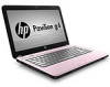
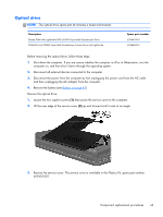
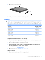
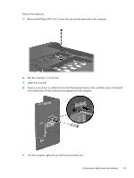
WLAN module Description For use on all computer models: Atheros 9285G 802.11b/g/n 1×1 WiFi Adapter Broadcom 4313 802.11b/g/n 1×1 WiFi and 2070 Bluetooth 2.1+EDR Combo Adapter (Bluetooth 3.0+HS ready) Ralink RT3090BC4 802.11b/g/n 1×1 WiFi and Bluetooth 2.1+EDR Combo Adapter (Bluetooth 3.0+HS ready) Broadcom 4313 802.11b/g/n 1×1 WiFi Adapter for use only on computer models equipped with an AMD processor Intel Centrino Wireless-N 1000 for use only on computer models equipped with an Intel processor Ralink 5390GN 802.11b/g/n 1×1 WiFi Adapter for use only on computer models equipped with an Intel processor Spare part number 605560-005 600370-001 630705-001 593836-001 593530-001 630703-001 CAUTION: To prevent an unresponsive system, replace the wireless module only with a wireless module authorized for use in the computer by the governmental agency that regulates wireless devices in your country or region. If you replace the module and then receive a warning message, remove the module to restore device functionality, and then contact technical support. Before removing the WLAN module, follow these steps: 1. Shut down the computer. If you are unsure whether the computer is off or in Hibernation, turn the computer on, and then shut it down through the operating system. 2. Disconnect all external devices connected to the computer. 3. Disconnect the power from the computer by first unplugging the power cord from the AC outlet and then unplugging the AC adapter from the computer. 4. Remove the battery (see Battery on page 42). 5. Remove the service cover (see Optical drive on page 43). Remove the WLAN module: 1. Disconnect the WLAN antenna cables (1) from the terminals on the WLAN module. NOTE: The 1/black WLAN antenna cable is connected to the WLAN module 1/Main terminal. The 2/gray WLAN antenna cable is connected to the WLAN module 2/Aux terminal. 2. Remove the Phillips PM2.0×4.0 screw (2) that secures the WLAN module to the system board. (The WLAN module tilts up.) 48 Chapter 4 Removal and replacement procedures
-
 1
1 -
2
-
3
-
4
-
5
-
6
-
7
-
8
-
9
-
10
-
11
-
12
-
13
-
14
-
15
-
16
-
17
-
18
-
19
-
20
-
21
-
22
-
23
-
24
-
25
-
26
-
27
-
28
-
29
-
30
-
31
-
32
-
33
-
34
-
35
-
36
-
37
-
38
-
39
-
40
-
41
-
42
-
43
-
44
-
45
-
46
-
47
-
48
-
49
-
50
-
 51
51 -
 52
52 -
 53
53 -
 54
54 -
 55
55 -
 56
56 -
 57
57 -
 58
58 -
 59
59 -
 60
60 -
 61
61 -
62
-
63
-
64
-
65
-
66
-
67
-
68
-
69
-
70
-
71
-
72
-
73
-
74
-
75
-
76
-
77
-
78
-
79
-
80
-
81
-
82
-
83
-
84
-
85
-
86
-
87
-
88
-
89
-
90
-
91
-
92
-
93
-
94
-
95
-
96
-
97
-
98
-
99
-
100
-
101
-
102
-
103
-
104
-
105
-
106
-
107
-
108
-
109
-
110
-
111
-
112
-
113
-
114
-
115
-
116
-
117
-
118
-
119
-
120
-
121
-
122
-
123
-
124
-
125
 |
 |