HP Pavilion g4-1000 HP G4 Notebook PC - Maintenance and Service Guide - Page 83
and the four Phillips PM2.5×10.0 spring-loaded, Remove the three Phillips PM2.5×5.0 screws
 |
View all HP Pavilion g4-1000 manuals
Add to My Manuals
Save this manual to your list of manuals |
Page 83 highlights
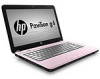
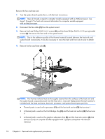
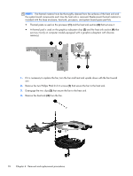
NOTE: Steps 5 through 7 apply to computer models equipped with an Intel processor. See steps 2 through 4 for heat sink removal information for computer models equipped with an AMD processor. 5. Disconnect the fan cable (1) from the system board. 6. Remove the three Phillips PM2.5×5.0 screws (2) and the four Phillips PM2.5×10.0 spring-loaded screws (3) that secure the heat sink to the system board. NOTE: Due to the adhesive quality of the thermal material located between the heat sink and system board components, it may be necessary to move the heat sink from side to side to detach it. 7. Remove the fan and heat sink (4). Component replacement procedures 75
-
 1
1 -
2
-
3
-
4
-
5
-
6
-
7
-
8
-
9
-
10
-
11
-
12
-
13
-
14
-
15
-
16
-
17
-
18
-
19
-
20
-
21
-
22
-
23
-
24
-
25
-
26
-
27
-
28
-
29
-
30
-
31
-
32
-
33
-
34
-
35
-
36
-
37
-
38
-
39
-
40
-
41
-
42
-
43
-
44
-
45
-
46
-
47
-
48
-
49
-
50
-
51
-
52
-
53
-
54
-
55
-
56
-
57
-
58
-
59
-
60
-
61
-
62
-
63
-
64
-
65
-
66
-
67
-
68
-
69
-
70
-
71
-
72
-
73
-
74
-
75
-
76
-
77
-
 78
78 -
 79
79 -
 80
80 -
 81
81 -
 82
82 -
 83
83 -
 84
84 -
 85
85 -
 86
86 -
 87
87 -
 88
88 -
89
-
90
-
91
-
92
-
93
-
94
-
95
-
96
-
97
-
98
-
99
-
100
-
101
-
102
-
103
-
104
-
105
-
106
-
107
-
108
-
109
-
110
-
111
-
112
-
113
-
114
-
115
-
116
-
117
-
118
-
119
-
120
-
121
-
122
-
123
-
124
-
125
 |
 |
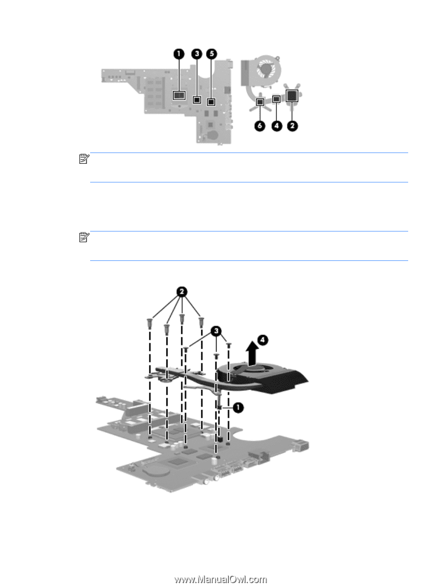
NOTE:
Steps 5 through 7 apply to computer models equipped with an Intel processor. See steps
2 through 4 for heat sink removal information for computer models equipped
with an AMD processor.
5.
Disconnect the fan cable
(1)
from the system board.
6.
Remove the three Phillips PM2.5×5.0 screws
(2)
and the four Phillips PM2.5×10.0 spring-loaded
screws
(3)
that secure the heat sink to the system board.
NOTE:
Due to the adhesive quality of the thermal material located between the heat sink and
system board components, it may be necessary to move the heat sink from side to side to detach
it.
7.
Remove the fan and heat sink
(4)
.
Component replacement procedures
75