HP Pavilion g4-1000 HP G4 Notebook PC - Maintenance and Service Guide - Page 71
from the clips built into the base enclosure., Remove the optical drive cable.
 |
View all HP Pavilion g4-1000 manuals
Add to My Manuals
Save this manual to your list of manuals |
Page 71 highlights
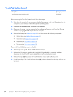
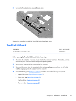
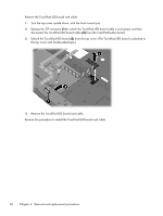
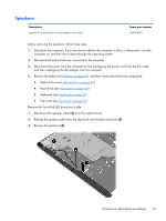
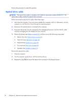
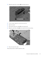
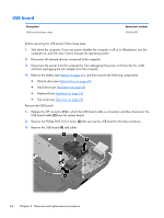
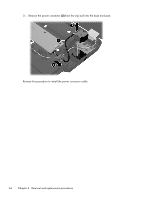
4. Release the optical drive connector (2) from the base enclosure. 5. Turn the computer right-side up, with the front toward you. 6. Open the computer. 7. Disconnect the optical drive cable (1) from the system board. 8. Release the optical drive cable (2) from the clips built into the base enclosure. 9. Remove the optical drive cable. Reverse this procedure to install the optical drive cable. Component replacement procedures 63
-
 1
1 -
2
-
3
-
4
-
5
-
6
-
7
-
8
-
9
-
10
-
11
-
12
-
13
-
14
-
15
-
16
-
17
-
18
-
19
-
20
-
21
-
22
-
23
-
24
-
25
-
26
-
27
-
28
-
29
-
30
-
31
-
32
-
33
-
34
-
35
-
36
-
37
-
38
-
39
-
40
-
41
-
42
-
43
-
44
-
45
-
46
-
47
-
48
-
49
-
50
-
51
-
52
-
53
-
54
-
55
-
56
-
57
-
58
-
59
-
60
-
61
-
62
-
63
-
64
-
65
-
 66
66 -
 67
67 -
 68
68 -
 69
69 -
 70
70 -
 71
71 -
 72
72 -
 73
73 -
 74
74 -
 75
75 -
 76
76 -
77
-
78
-
79
-
80
-
81
-
82
-
83
-
84
-
85
-
86
-
87
-
88
-
89
-
90
-
91
-
92
-
93
-
94
-
95
-
96
-
97
-
98
-
99
-
100
-
101
-
102
-
103
-
104
-
105
-
106
-
107
-
108
-
109
-
110
-
111
-
112
-
113
-
114
-
115
-
116
-
117
-
118
-
119
-
120
-
121
-
122
-
123
-
124
-
125
 |
 |

4.
Release the optical drive connector
(2)
from the base enclosure.
5.
Turn the computer right-side up, with the front toward you.
6.
Open the computer.
7.
Disconnect the optical drive cable
(1)
from the system board.
8.
Release the optical drive cable
(2)
from the clips built into the base enclosure.
9.
Remove the optical drive cable.
Reverse this procedure to install the optical drive cable.
Component replacement procedures
63