HP Pavilion zt1100 HP Pavilion Notebook PC ZE1000 Series - Reference Guide - Page 117
PTT testing of signal level: 00-09=DTMF dial 0-9, 0A=DTMF *, 0B=DTMF #, 0C=DTMF A, 0D=DTMF B
 |
View all HP Pavilion zt1100 manuals
Add to My Manuals
Save this manual to your list of manuals |
Page 117 highlights
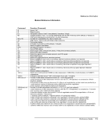
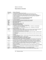
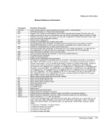
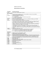
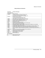
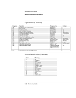
Modem Reference Information Reference Information Command -QCPS=n &Cn &Dn &En &F0 &Gn &Kn &Mn &Pn &Q5 &Qn &T0 &T1 &V %TTn \N0 \N1 \N2 \N3 \N4 \N5 +MCR +MMR +MR=0 +MR=1 +MR=2 +MS=a,b,c,d,e,f Function (Conexant) 0=do not allow modem to save generated quick-connect profile, 1=allow (default) Set RLSD: 0=always on, 1=follow carrier state (default). 0=ignore DTR; 1=upon on-to-off transition, enter online command state and issue OK result code; call remains connected; 2=upon on-to-off transition clear call, discard untransmitted data according to +ETBM. 0=disable line quality monitor, auto-retrain, and auto-rate renegotiation;1=enable line quality monitor, autoretrain, and auto-rate renegotiation (default). Restore factory configuration. Included for compatibility only; no effect (returns OK). Set DTE/DCE flow control: 0=disable, 3=enable RTS/CTS DTE/DCE flow control (default), 4=enable XON/XOFF DTE/DCE flow control, 5 and 6 included for compatibility only (no effect, returns OK). Included for compatibility only; no effect (returns result code). Set pulse dial (pps) with make/break: 0=10 pps with 39%-61% make/break (default), 1=10 pps with 33%- 67% make/break, 2=20 pps with 39%-61% make/break, 3=20 pps with 33%-67% make/break. Select asynchronous operation in error correction mode. (n=0-3, 6) Select asynchronous operation in normal mode (speed buffering). Terminate any test in progress. Initiate local analog loopback. Display current configuration and stored profiles. PTT testing of signal level: 00-09=DTMF dial 0-9, 0A=DTMF *, 0B=DTMF #, 0C=DTMF A, 0D=DTMF B, 0E=DTMF C, 0F=DTMF D, 10=V.21 Channel 1mark symbol, 11=V.21 Channel 2mark symbol, 12=V.23 Channel 1mark symbol, 13=V.23 Channel 2mark symbol, 14=Bell103 Channel 1mark symbol, 15=Bell103 Channel 2mark symbol, 20=V22Org, 21=V22Ans, 22=Bell212Org, 23=Bell212Ans, 24=V22BisOrg, 25=V22BisAns, 26=V32@4800, 27=V32@7200, 28=V32@9600, 29=V.32Bis@12000, 2A=V32Bis@14400, 30=Silence, 31=2100Hz MISC, 33=1300Hz MISC, 34=1100Hz MISC, 40=Reserved, 41=V27@2400 FAX, 42=V27@4800 FAX, 43=V29@7200 FAX, 44=V29@9600 FAX, 45=V17@7200LT FAX, 46=V17@7200ST FAX, 47=V17@9600LT FAX, 48=V17@9600ST FAX, 49=V17@12000LT FAX, 4A=V17@12000ST FAX, 4B=V17@14400LT FAX, 4C=V17@14400ST FAX. 5abc: a=bit rate (0=2400, D=33600), b=V.34 symbol rate (0=2400, 5=3429), c=pre-emphasis filter (0 to A). When modem receives break from the remote modem: Select normal speed buffered mode. Select normal speed buffered mode. Select reliable (error-correction) mode. Select auto reliable mode. Force LAPM mode. Force MNP mode. Report carrier. Report transmit and receive rates. Disable reporting of modulation connection. Enable reporting of modulation connection (+MCR: and +MRR: are transmitted) (default). Enable reporting of modulation connection (+MCR: and Receive Rate Only: are transmitted). Select modulation (b, c, d, e, and f are optional). a is the carrier (allowable rates in parentheses): B103 (300), B212 (1200 Rx/75 Tx or 75 Rx/1200 Tx), V21 (300), V22 (1200), V22B (1200/2400), V23C (1200), V32 (4800/9600), V32B (4800-14400), V34 (2400- 33600), K56 (32000-56000), V90 (28000-56000), V92 (downstream: 28000-56000; upstream: 24000- 48000). b is automode: 0=disabled, 1=enabled (default). c is minimum transmit (Tx) rate (bps). d is maximum transmit rate (bps). e is minimum receive (Rx) rate. f is maximum receive rate (bps). Reference Guide 117
-
 1
1 -
2
-
3
-
4
-
5
-
6
-
7
-
8
-
9
-
10
-
11
-
12
-
13
-
14
-
15
-
16
-
17
-
18
-
19
-
20
-
21
-
22
-
23
-
24
-
25
-
26
-
27
-
28
-
29
-
30
-
31
-
32
-
33
-
34
-
35
-
36
-
37
-
38
-
39
-
40
-
41
-
42
-
43
-
44
-
45
-
46
-
47
-
48
-
49
-
50
-
51
-
52
-
53
-
54
-
55
-
56
-
57
-
58
-
59
-
60
-
61
-
62
-
63
-
64
-
65
-
66
-
67
-
68
-
69
-
70
-
71
-
72
-
73
-
74
-
75
-
76
-
77
-
78
-
79
-
80
-
81
-
82
-
83
-
84
-
85
-
86
-
87
-
88
-
89
-
90
-
91
-
92
-
93
-
94
-
95
-
96
-
97
-
98
-
99
-
100
-
101
-
102
-
103
-
104
-
105
-
106
-
107
-
108
-
109
-
110
-
111
-
 112
112 -
 113
113 -
 114
114 -
 115
115 -
 116
116 -
 117
117 -
 118
118 -
 119
119 -
 120
120 -
 121
121 -
 122
122 -
123
-
124
-
125
-
126
-
127
-
128
-
129
 |
 |