HP rp8420 Installation Guide, Fifth Edition - HP 9000 rp8420 Server - Page 16
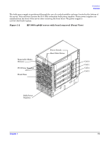
HP 9000 rp8420 server with top cover removed Rear View, PCI I/O Card
 |
View all HP rp8420 manuals
Add to My Manuals
Save this manual to your list of manuals |
Page 16 highlights
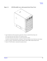
Introduction Overview Figure 1-3 HP 9000 rp8420 server with top cover removed (Rear View) PCI OLR Fans PCI I/O Card Section Core I/O Cards Rear OLR Fans AC Power Receptacles See Figure 1-3 for component locations described below. The PCI-X I/O card section, located in upper rear of server, is accessed by removing the top cover. The PCI-X OLR fan modules are located opposite PCI-X card bulkheads. They are housed in blue plastic carriers. The two redundant core I/O cards are positioned vertically, one above the other, at the rear of the chassis. The PCI-X card bulkhead connectors are located at the top rear. The 12 rear OLR fans house 120-mm exhaust fans. Redundant power line cords attach to the AC power receptacles at the bottom rear. Two 20-amp cords are required to power the HP 9000 rp8420 server. Two additional 20-amp cords provide redundancy. When facing the front of the server, access the system backplane by removing the left side cover (cover shown installed in figure). The system backplane hinges from the lower edge and is anchored at the top with a large blue, single jack screw assembly. The SCSI ribbon cable assembly (not shown in figure) is connected on the opposite side of the cell board connectors of the system backplane, towards the rear of the server near the core I/O boards. The blue deployment handles at the base of the server sides (not shown in figure) hinge outward to manually lift and place the server onto a cabinet slide rack. 16 Chapter 1
-
 1
1 -
2
-
3
-
4
-
5
-
6
-
7
-
8
-
9
-
10
-
 11
11 -
 12
12 -
 13
13 -
 14
14 -
 15
15 -
 16
16 -
 17
17 -
 18
18 -
 19
19 -
 20
20 -
 21
21 -
22
-
23
-
24
-
25
-
26
-
27
-
28
-
29
-
30
-
31
-
32
-
33
-
34
-
35
-
36
-
37
-
38
-
39
-
40
-
41
-
42
-
43
-
44
-
45
-
46
-
47
-
48
-
49
-
50
-
51
-
52
-
53
-
54
-
55
-
56
-
57
-
58
-
59
-
60
-
61
-
62
-
63
-
64
-
65
-
66
-
67
-
68
-
69
-
70
-
71
-
72
-
73
-
74
-
75
-
76
-
77
-
78
-
79
-
80
 |
 |
