HP rp8420 Installation Guide, Fifth Edition - HP 9000 rp8420 Server - Page 38
Securing Each Caster Cover to the Server, Step 15.
 |
View all HP rp8420 manuals
Add to My Manuals
Save this manual to your list of manuals |
Page 38 highlights
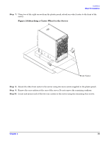
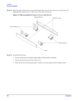
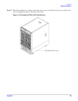
Installation Wheel Kit Installation Step 15. Insert the slot on the caster cover into the front caster. Secure the caster cover to the server by tightening the captive screw on the cover at the rear of the server. Figure 2-12Securing Each Caster Cover to the Server Captive Screw Caster Covers Rear Casters Front Casters Slot Step 16. Install the front bezel. • Locate and mount the 4 plastic spring clips on front corners of chassis. • Orient the bezel onto the front of the server. • Push the bezel onto the spring clips on either side of the chassis until it snaps in place. 38 Chapter 2
-
 1
1 -
2
-
3
-
4
-
5
-
6
-
7
-
8
-
9
-
10
-
11
-
12
-
13
-
14
-
15
-
16
-
17
-
18
-
19
-
20
-
21
-
22
-
23
-
24
-
25
-
26
-
27
-
28
-
29
-
30
-
31
-
32
-
 33
33 -
 34
34 -
 35
35 -
 36
36 -
 37
37 -
 38
38 -
 39
39 -
 40
40 -
 41
41 -
 42
42 -
 43
43 -
44
-
45
-
46
-
47
-
48
-
49
-
50
-
51
-
52
-
53
-
54
-
55
-
56
-
57
-
58
-
59
-
60
-
61
-
62
-
63
-
64
-
65
-
66
-
67
-
68
-
69
-
70
-
71
-
72
-
73
-
74
-
75
-
76
-
77
-
78
-
79
-
80
 |
 |

Chapter 2
Installation
Wheel Kit Installation
38
Step 15.
Insert the slot on the caster cover into the front caster. Secure the caster cover to the server by
tightening the captive screw on the cover at the rear of the server.
Figure 2-12Securing Each Caster Cover to the Server
Step 16.
Install the front bezel.
•
Locate and mount the 4 plastic spring clips on front corners of chassis.
•
Orient the bezel onto the front of the server.
•
Push the bezel onto the spring clips on either side of the chassis until it snaps in place.
Caster Covers
Front Casters
Slot
Captive Screw
Rear Casters