HP rp8420 Installation Guide, Fifth Edition - HP 9000 rp8420 Server - Page 54
Voltage Check (Additional Procedure), Wall Receptacle Pinouts
 |
View all HP rp8420 manuals
Add to My Manuals
Save this manual to your list of manuals |
Page 54 highlights
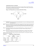
Installation Cabling and Power Up Voltage Check (Additional Procedure) The voltage check ensures that all phases (and neutral, for international systems) are connected correctly to the cabinet and that the AC input voltage is within limits. Perform this procedure if the previous voltage check procedure did not yield the expected results as previously outlined. NOTE If a UPS is used, refer to applicable UPS documentation for information on connecting the server and checking the UPS output voltage. UPS User Manual documentation is shipped with the UPS. Documentation can also be found at http://www.hp.com/racksolutions Step 1. Verify that site power is OFF. Step 2. Open the site circuit breakers. Step 3. Verify that the receptacle ground connector is connected to ground. See Figure 2-22 for connector details. Step 4. Set the site power circuit breaker to ON. Figure 2-22 Wall Receptacle Pinouts X Y XY X GY X Y GND CEE 7/7 GND IEC 309/16A GND L6 - 20 GND GB - 1002 Step 5. Verify that the voltage between receptacle pins X and Y is between 200-240 VAC. Step 6. Set the site power circuit breaker to OFF. Step 7. Ensure that power is removed from the server. Step 8. Route and connect the server power connector to the site power receptacle. a. For locking type receptacles, line up the key on the plug with the groove in the receptacle. b. Push the plug into the receptacle and rotate to lock the connector in place. WARNING Do not set site AC circuit breakers serving the processor cabinets to ON before verifying that the cabinet has been wired into the site AC power supply correctly. Failure to do so can result in injury to personnel or damage to equipment when AC power is applied to the cabinet. Step 9. Set the site power circuit breaker to ON. 54 Chapter 2
-
 1
1 -
2
-
3
-
4
-
5
-
6
-
7
-
8
-
9
-
10
-
11
-
12
-
13
-
14
-
15
-
16
-
17
-
18
-
19
-
20
-
21
-
22
-
23
-
24
-
25
-
26
-
27
-
28
-
29
-
30
-
31
-
32
-
33
-
34
-
35
-
36
-
37
-
38
-
39
-
40
-
41
-
42
-
43
-
44
-
45
-
46
-
47
-
48
-
 49
49 -
 50
50 -
 51
51 -
 52
52 -
 53
53 -
 54
54 -
 55
55 -
 56
56 -
 57
57 -
 58
58 -
 59
59 -
60
-
61
-
62
-
63
-
64
-
65
-
66
-
67
-
68
-
69
-
70
-
71
-
72
-
73
-
74
-
75
-
76
-
77
-
78
-
79
-
80
 |
 |
