HP rp8420 Installation Guide, Fifth Edition - HP 9000 rp8420 Server - Page 63
Turning On Housekeeping Power and Logging In to the MP,
 |
View all HP rp8420 manuals
Add to My Manuals
Save this manual to your list of manuals |
Page 63 highlights
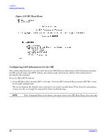
Installation Cabling and Power Up 1. Connect one end of a null modem cable (9-pin to 9-pin) (Part Number 5182-4794) to the Local RS-232 port on the core I/O card (the DB9 connector located at the bottom of the core I/O card). Figure 2-27 LAN and RS-232 Connectors on the Core I/O Board Core I/O Card UPS (Optional) or Other Serial Device Customer Lan Modem Note: The ability to telnet to the MP LAN Port is available once the MP is configured via the RS-232 Local Port Cable Part # 5182-4794 CE Tool (PC) RS-232 UPS System LAN (Customer LAN) ( Assigned /dev/lan0 ) RS-232 Remote MP LAN ( Assigned /dev/lan1 ) RS-232 Local KIN001 5/23/01 2. Connect the other end of the RS-232 cable to the CE Tool. Turning On Housekeeping Power and Logging In to the MP After connecting the serial display device, the power to the server cabinet is ready to be supplied to get a login prompt for the MP. Connecting the power cords allows power to flow to the BPS located at the front of the server cabinet, which in turn provides housekeeping power (HKP). Before powering up the server cabinet for the first time: 1. Verify that the AC voltage at the input source is within specifications for each server cabinet being installed. 2. If not already done, power on the serial display device. The preferred tool is the CE Tool running Reflection 1. To power on the MP, set up a communications link, and log in to the MP: Chapter 2 63
-
 1
1 -
2
-
3
-
4
-
5
-
6
-
7
-
8
-
9
-
10
-
11
-
12
-
13
-
14
-
15
-
16
-
17
-
18
-
19
-
20
-
21
-
22
-
23
-
24
-
25
-
26
-
27
-
28
-
29
-
30
-
31
-
32
-
33
-
34
-
35
-
36
-
37
-
38
-
39
-
40
-
41
-
42
-
43
-
44
-
45
-
46
-
47
-
48
-
49
-
50
-
51
-
52
-
53
-
54
-
55
-
56
-
57
-
 58
58 -
 59
59 -
 60
60 -
 61
61 -
 62
62 -
 63
63 -
 64
64 -
 65
65 -
 66
66 -
 67
67 -
 68
68 -
69
-
70
-
71
-
72
-
73
-
74
-
75
-
76
-
77
-
78
-
79
-
80
 |
 |
