HP t530 Hardware Reference Guide - Page 40
Power-On Sequence, Resetting the Setup and Power-on passwords, Power-on diagnostic tests
 |
View all HP t530 manuals
Add to My Manuals
Save this manual to your list of manuals |
Page 40 highlights
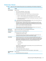
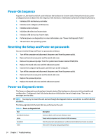
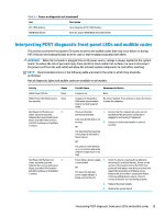
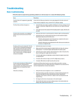
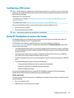
Power-On Sequence At power-on, the flash boot block code initializes the hardware to a known state, then performs basic poweron diagnostic tests to determine the integrity of the hardware. Initialization performs the following functions: 1. Initializes CPU and memory controller. 2. Initializes and configures all PCI devices. 3. Initializes video software. 4. Initializes the video to a known state. 5. Initializes USB devices to a known state. 6. Performs power-on diagnostics. For more information, see "Power-On Diagnostic Tests". 7. The unit boots the operating system. Resetting the Setup and Power-on passwords You can reset the Setup and Power-on passwords as follows: 1. Turn off the computer and disconnect the power cord from the power outlet. 2. Remove the side access panel and the metal side cover. 3. Remove the password jumper from the system board header labeled PSWD/E49. 4. Replace the metal side cover and the side access panel. 5. Connect the computer to AC power, and then turn on the computer. 6. Turn off the computer and disconnect the power cord from the power outlet. 7. Remove the side access panel and the metal side cover. 8. Replace the password jumper. 9. Replace the metal side cover and the side access panel. Power-on diagnostic tests The Power-on diagnostics performs basic integrity tests of the hardware to determine its functionality and configuration. If a diagnostic test fails during hardware initialization the unit simply stops. There are no messages sent to video. NOTE: You may try to restart the unit and run through the diagnostic tests a second time to confirm the first shutdown. The following table lists the tests that are performed on the unit. Table 2-1 Power-on diagnostic test Test Description Boot Block Checksum DRAM Serial Port Timer Tests boot block code for proper checksum value Simple write/read pattern test of the first 640k of memory Tests the serial port using simple port verification test to determine if ports are present Tests timer interrupt by using polling method 34 Chapter 2 Troubleshooting
-
 1
1 -
2
-
3
-
4
-
5
-
6
-
7
-
8
-
9
-
10
-
11
-
12
-
13
-
14
-
15
-
16
-
17
-
18
-
19
-
20
-
21
-
22
-
23
-
24
-
25
-
26
-
27
-
28
-
29
-
30
-
31
-
32
-
33
-
34
-
 35
35 -
 36
36 -
 37
37 -
 38
38 -
 39
39 -
 40
40 -
 41
41 -
 42
42 -
 43
43 -
 44
44 -
 45
45 -
46
-
47
-
48
-
49
-
50
-
51
-
52
-
53
-
54
-
55
-
56
 |
 |
