Hitachi HTS541680J9AT00 Specifications - Page 38
Signal definitions - 20
 |
UPC - 683728200794
View all Hitachi HTS541680J9AT00 manuals
Add to My Manuals
Save this manual to your list of manuals |
Page 38 highlights
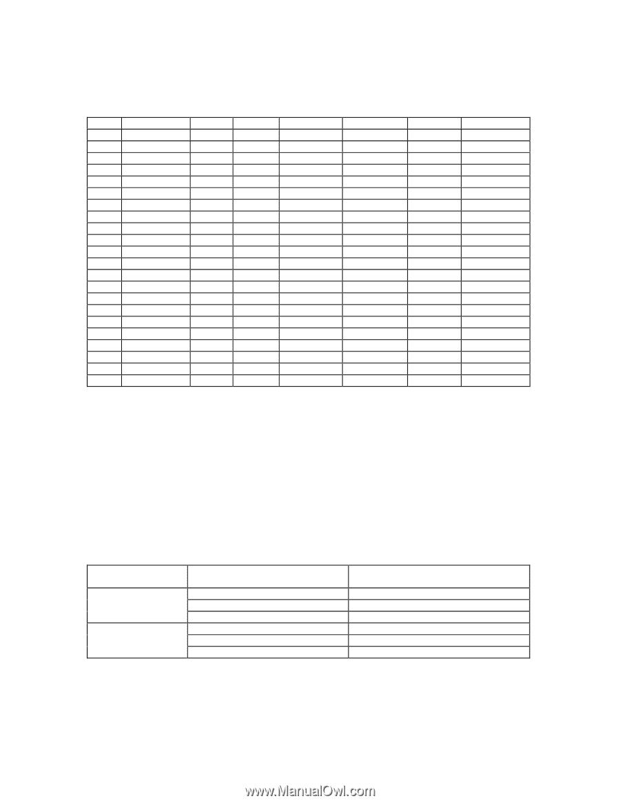
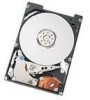
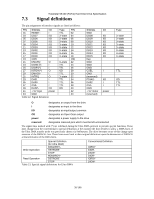
Travelstar 5K160 (PATA) Hard Disk Drive Specification 7.3 Signal definitions The pin assignments of interface signals are listed as follows: PIN SIGNAL I/O Type PIN 01 RESET- I TTL 02 03 DD07 I/O 3-state 04 05 DD06 I/O 3-state 06 07 DD05 I/O 3-state 08 09 DD04 I/O 3-state 10 11 DD03 I/O 3-state 12 13 DD02 I/O 3-state 14 15 DD01 I/O 3-state 16 17 DD00 I/O 3-state 18 19 GND (20) 21 DMARQ O 3-state 22 23 DIOW-(*) I TTL 24 25 DIOR-(*) I TTL 26 27 IORDY(*) O OD 28 29 DMACK- I TTL 30 31 INTRQ O 3-state 32 33 DA01 I TTL 34 35 DA00 I TTL 36 37 CS0- I TTL 38 39 DASP- I/O OD 40 41 + 5V logic power 42 43 GND 44 Table 22. Signal definition SIGNAL GND DD08 DD09 DD10 DD11 DD12 DD13 DD14 DD15 Key GND GND GND CSEL GND (reserved) PDIAGDA02 CS1GND + 5V motor (reserved) I/O I/O I/O I/O I/O I/O I/O I/O I/O I I/O I I power Type 3-state 3-state 3-state 3-state 3-state 3-state 3-state 3-state TTL OD TTL TTL O designates an output from the drive I designates an input to the drive I/O designates an input/output common OD designates an Open-Drain output power designates a power supply to the drive reserved designates reserved pins which must be left unconnected The signal lines marked with (*) are redefined during the Ultra DMA protocol to provide special functions. These lines change from the conventional to special definitions at the moment the host decides to allow a DMA burst, if the Ultra DMA transfer mode was previously chosen via SetFeatures. The drive becomes aware of this change upon assertion of the DMACK- line. These lines revert back to their original definitions upon the deassertion of DMACK at the termination of the DMA burst. Special Definition (for Ultra DMA) DDMARDY- Write Operation HSTROBE STOP HDMARDY- Read Operation DSTROBE STOP Table 23. Special signal definitions for Ultra DMA Conventional Definition IORDY DIORDIOWDIORIORDY DIOW- 38/188
-
 1
1 -
2
-
3
-
4
-
5
-
6
-
7
-
8
-
9
-
10
-
11
-
12
-
13
-
14
-
15
-
16
-
17
-
18
-
19
-
20
-
21
-
22
-
23
-
24
-
25
-
26
-
27
-
28
-
29
-
30
-
31
-
32
-
 33
33 -
 34
34 -
 35
35 -
 36
36 -
 37
37 -
 38
38 -
 39
39 -
 40
40 -
 41
41 -
 42
42 -
 43
43 -
44
-
45
-
46
-
47
-
48
-
49
-
50
-
51
-
52
-
53
-
54
-
55
-
56
-
57
-
58
-
59
-
60
-
61
-
62
-
63
-
64
-
65
-
66
-
67
-
68
-
69
-
70
-
71
-
72
-
73
-
74
-
75
-
76
-
77
-
78
-
79
-
80
-
81
-
82
-
83
-
84
-
85
-
86
-
87
-
88
-
89
-
90
-
91
-
92
-
93
-
94
-
95
-
96
-
97
-
98
-
99
-
100
-
101
-
102
-
103
-
104
-
105
-
106
-
107
-
108
-
109
-
110
-
111
-
112
-
113
-
114
-
115
-
116
-
117
-
118
-
119
-
120
-
121
-
122
-
123
-
124
-
125
-
126
-
127
-
128
-
129
-
130
-
131
-
132
-
133
-
134
-
135
-
136
-
137
-
138
-
139
-
140
-
141
-
142
-
143
-
144
-
145
-
146
-
147
-
148
-
149
-
150
-
151
-
152
-
153
-
154
-
155
-
156
-
157
-
158
-
159
-
160
-
161
-
162
-
163
-
164
-
165
-
166
-
167
-
168
-
169
-
170
-
171
-
172
-
173
-
174
-
175
-
176
-
177
-
178
-
179
-
180
-
181
-
182
-
183
-
184
-
185
-
186
-
187
-
188
 |
 |