Hitachi HTS541680J9AT00 Specifications - Page 61
Sector Count Register, Status Register
 |
UPC - 683728200794
View all Hitachi HTS541680J9AT00 manuals
Add to My Manuals
Save this manual to your list of manuals |
Page 61 highlights
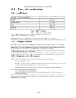
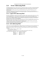
Travelstar 5K160 (PATA) Hard Disk Drive Specification 11.12 Sector Count Register This register contains the number of sectors of data requested to be transferred on a read or write operation between the host and the device. If the value in the register is set to 0, a count of 256 sectors (in 28-bit addressing) or 65,536 sectors (in 48-bit addressing) is specified. If the register is zero at command completion, the command was successful. If not successfully completed, the register contains the number of sectors which need to be transferred in order to complete the request. The contents of the register are defined otherwise on some commands. These definitions are given in the command descriptions. 11.13 Status Register 7 6 5 BSY DRDY DF Figure 22 Status Register Status Register 4 3 2 1 0 DSC DRQ CORR IDX ERR This register contains the device status. The contents of this register are updated whenever an error occurs and at the completion of each command. If the host reads this register when an interrupt is pending, it is considered to be the interrupt acknowledge. Any pending interrupt is cleared whenever this register is read. If BSY=1, no other bits in the register are valid. Bit Definitions BSY Busy. BSY=1 whenever the device is accessing the registers. The host should not read or write any registers when BSY=1. If the host reads any register when BSY=1, the contents of the Status Register will be returned. DRDY (RDY) Device Ready. RDY=1 indicates that the device is capable of responding to a command. RDY will be set to 0 during power on until the device is ready to accept a command. DF Device Fault. DF=1 indicates that the device has detected a write fault condition. DF is set to 0 after the Status Register is read by the host. DSC Device Seek Complete. DSC=1 indicates that a seek has completed and the device head is settled over a track. DSC is set to 0 by the device just before a seek begins. When an error occurs, this bit is not changed until the Status Register is read by the host, at which time the bit again indicates the current seek complete status. When the device enters into or is in Standby mode or Sleep mode, this bit is set by device in spite of not spinning up. DRQ Data Request. DRQ=1 indicates that the device is ready to transfer a word or byte of data between the host and the device. The host should not write the Command register when DRQ=1. CORR (COR) Corrected Data. Always 0. IDX Index. IDX=1 once per revolution. Since IDX=1 only for a very short time during each revolution, the host may not see it set to 1 even if the host is reading the Status Register continuously. Therefore the host should not attempt to use IDX for timing purposes. ERR ERR=1 indicates that an error occurred during execution of the previous command. The Error Register should be read to determine the error type. The device sets ERR=0 when the next command is received from the host. 61/188
-
 1
1 -
2
-
3
-
4
-
5
-
6
-
7
-
8
-
9
-
10
-
11
-
12
-
13
-
14
-
15
-
16
-
17
-
18
-
19
-
20
-
21
-
22
-
23
-
24
-
25
-
26
-
27
-
28
-
29
-
30
-
31
-
32
-
33
-
34
-
35
-
36
-
37
-
38
-
39
-
40
-
41
-
42
-
43
-
44
-
45
-
46
-
47
-
48
-
49
-
50
-
51
-
52
-
53
-
54
-
55
-
 56
56 -
 57
57 -
 58
58 -
 59
59 -
 60
60 -
 61
61 -
 62
62 -
 63
63 -
 64
64 -
 65
65 -
 66
66 -
67
-
68
-
69
-
70
-
71
-
72
-
73
-
74
-
75
-
76
-
77
-
78
-
79
-
80
-
81
-
82
-
83
-
84
-
85
-
86
-
87
-
88
-
89
-
90
-
91
-
92
-
93
-
94
-
95
-
96
-
97
-
98
-
99
-
100
-
101
-
102
-
103
-
104
-
105
-
106
-
107
-
108
-
109
-
110
-
111
-
112
-
113
-
114
-
115
-
116
-
117
-
118
-
119
-
120
-
121
-
122
-
123
-
124
-
125
-
126
-
127
-
128
-
129
-
130
-
131
-
132
-
133
-
134
-
135
-
136
-
137
-
138
-
139
-
140
-
141
-
142
-
143
-
144
-
145
-
146
-
147
-
148
-
149
-
150
-
151
-
152
-
153
-
154
-
155
-
156
-
157
-
158
-
159
-
160
-
161
-
162
-
163
-
164
-
165
-
166
-
167
-
168
-
169
-
170
-
171
-
172
-
173
-
174
-
175
-
176
-
177
-
178
-
179
-
180
-
181
-
182
-
183
-
184
-
185
-
186
-
187
-
188
 |
 |
