IBM 306m User Guide - Page 20
Server, power, features - processor
 |
UPC - 000435867605
View all IBM 306m manuals
Add to My Manuals
Save this manual to your list of manuals |
Page 20 highlights
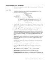
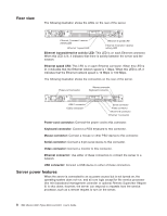
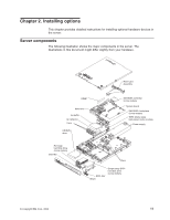
Rear view The following illustration shows the LEDs on the rear of the server. Ethernet 1 transmit / receive activity LED Ethernet 1 speed LED Ethernet 2 speed LED Ethernet 2 transmit / receive activity LED Ethernet transmit/receive activity LED: This LED is on each Ethernet connector. When this LED is lit, it indicates that there is activity between the server and the network. Ethernet speed LED: This LED is on each Ethernet connector. When this LED is lit, it indicates that the Ethernet network speed is 1 Gbps. When this LED is off, it indicates that the Ethernet network speed is 10 Mbps or 100 Mbps. The following illustration shows the connectors on the rear of the server. Power-cord connector Mouse connector Keyboard connector USB 1 connector USB 2 connector Serial connector Video connector Ethernet 2 connector Ethernet 1 connector Power-cord connector: Connect the power cord to this connector. Keyboard connector: Connect a PS/2 keyboard to this connector. Mouse connector: Connect a mouse or other PS/2 device to this connector. Serial connector: Connect a 9-pin serial device to this connector. Video connector: Connect a monitor to this connector. Ethernet connector: Use either of these connectors to connect the server to a network. USB connector: Connect a USB device to either of these connectors. Server power features When the server is connected to an ac power source but is not turned on, the operating system does not run, and all core logic except for the service processor (the mini-baseboard management controller or optional Remote Supervisor Adapter II) is shut down; however, the server can respond to requests from the service processor, such as a remote request to turn on the server. 8 IBM xSeries 306m Types 8849 and 8491: User's Guide
-
 1
1 -
2
-
3
-
4
-
5
-
6
-
7
-
8
-
9
-
10
-
11
-
12
-
13
-
14
-
 15
15 -
 16
16 -
 17
17 -
 18
18 -
 19
19 -
 20
20 -
 21
21 -
 22
22 -
 23
23 -
 24
24 -
 25
25 -
26
-
27
-
28
-
29
-
30
-
31
-
32
-
33
-
34
-
35
-
36
-
37
-
38
-
39
-
40
-
41
-
42
-
43
-
44
-
45
-
46
-
47
-
48
-
49
-
50
-
51
-
52
-
53
-
54
-
55
-
56
-
57
-
58
-
59
-
60
-
61
-
62
-
63
-
64
-
65
-
66
-
67
-
68
-
69
-
70
-
71
-
72
-
73
-
74
 |
 |
