IBM 306m User Guide - Page 28
System-board, option, connectors
 |
UPC - 000435867605
View all IBM 306m manuals
Add to My Manuals
Save this manual to your list of manuals |
Page 28 highlights
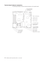
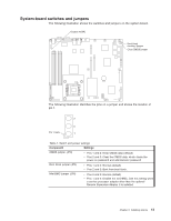
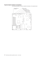
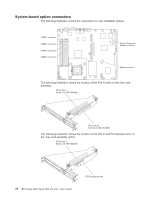
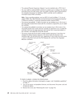
System-board option connectors The following illustration shows the connectors for user-installable options. The following illustration shows the location of the PCI-X slots on the riser-card assembly. PCI-X slot 1 64-bit 3.3 V 66/100 MHz PCI-X slot 2 64-bit 3.3 V 66/100 MHz The following illustration shows the location of the PCI-X and PCI Express slots on the riser-card assembly option. PCI-X slot 1 64-bit 3.3 V 66/100 MHz 16 IBM xSeries 306m Types 8849 and 8491: User's Guide PCI Express x8 slot
-
 1
1 -
2
-
3
-
4
-
5
-
6
-
7
-
8
-
9
-
10
-
11
-
12
-
13
-
14
-
15
-
16
-
17
-
18
-
19
-
20
-
21
-
22
-
 23
23 -
 24
24 -
 25
25 -
 26
26 -
 27
27 -
 28
28 -
 29
29 -
 30
30 -
 31
31 -
 32
32 -
 33
33 -
34
-
35
-
36
-
37
-
38
-
39
-
40
-
41
-
42
-
43
-
44
-
45
-
46
-
47
-
48
-
49
-
50
-
51
-
52
-
53
-
54
-
55
-
56
-
57
-
58
-
59
-
60
-
61
-
62
-
63
-
64
-
65
-
66
-
67
-
68
-
69
-
70
-
71
-
72
-
73
-
74
 |
 |

System-board
option
connectors
The
following
illustration
shows
the
connectors
for
user-installable
options.
The
following
illustration
shows
the
location
of
the
PCI-X
slots
on
the
riser-card
assembly.
PCI-X slot 1
64-bit 3.3 V 66/100 MHz
PCI-X slot 2
64-bit 3.3 V 66/100 MHz
The
following
illustration
shows
the
location
of
the
PCI-X
and
PCI
Express
slots
on
the
riser-card
assembly
option.
PCI-X slot 1
64-bit 3.3 V 66/100 MHz
PCI Express x8 slot
16
IBM
xSeries
306m
Types
8849
and
8491:
User’s
Guide