IBM 306m User Guide - Page 25
System-board, switches, jumpers
 |
UPC - 000435867605
View all IBM 306m manuals
Add to My Manuals
Save this manual to your list of manuals |
Page 25 highlights
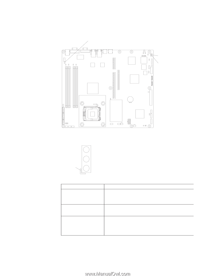
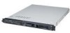
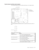
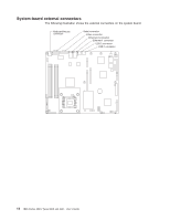
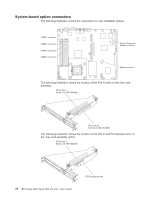
System-board switches and jumpers The following illustration shows the switches and jumpers on the system board. Disable mBMC Boot block recovery jumper Clear CMOS jumper The following illustration identifies the pins on a jumper and shows the location of pin 1. 3 2 Pin 1 mark 1 Table 2. Switch and jumper settings Component Settings CMOS jumper (JP3) v Pins 1 and 2: Keep CMOS data (default) v Pins 2 and 3: Clear the CMOS data, which clears the power-on password and administrator password Boot block jumper (JP4) v Pins 1 and 2: Normal (default) v Pins 2 and 3: Boot from boot block. Mini-BMC jumper (JP6) v Pins 2 and 3: Normal (default) v Pins 1 and 2: Disable the mini-BMC. Use this setting when a service processor adapter other than the optional Remote Supervisor Adapter II is installed. Chapter 2. Installing options 13
-
 1
1 -
2
-
3
-
4
-
5
-
6
-
7
-
8
-
9
-
10
-
11
-
12
-
13
-
14
-
15
-
16
-
17
-
18
-
19
-
 20
20 -
 21
21 -
 22
22 -
 23
23 -
 24
24 -
 25
25 -
 26
26 -
 27
27 -
 28
28 -
 29
29 -
 30
30 -
31
-
32
-
33
-
34
-
35
-
36
-
37
-
38
-
39
-
40
-
41
-
42
-
43
-
44
-
45
-
46
-
47
-
48
-
49
-
50
-
51
-
52
-
53
-
54
-
55
-
56
-
57
-
58
-
59
-
60
-
61
-
62
-
63
-
64
-
65
-
66
-
67
-
68
-
69
-
70
-
71
-
72
-
73
-
74
 |
 |