IBM 306m User Guide - Page 38
random-access - specifications
 |
UPC - 000435867605
View all IBM 306m manuals
Add to My Manuals
Save this manual to your list of manuals |
Page 38 highlights
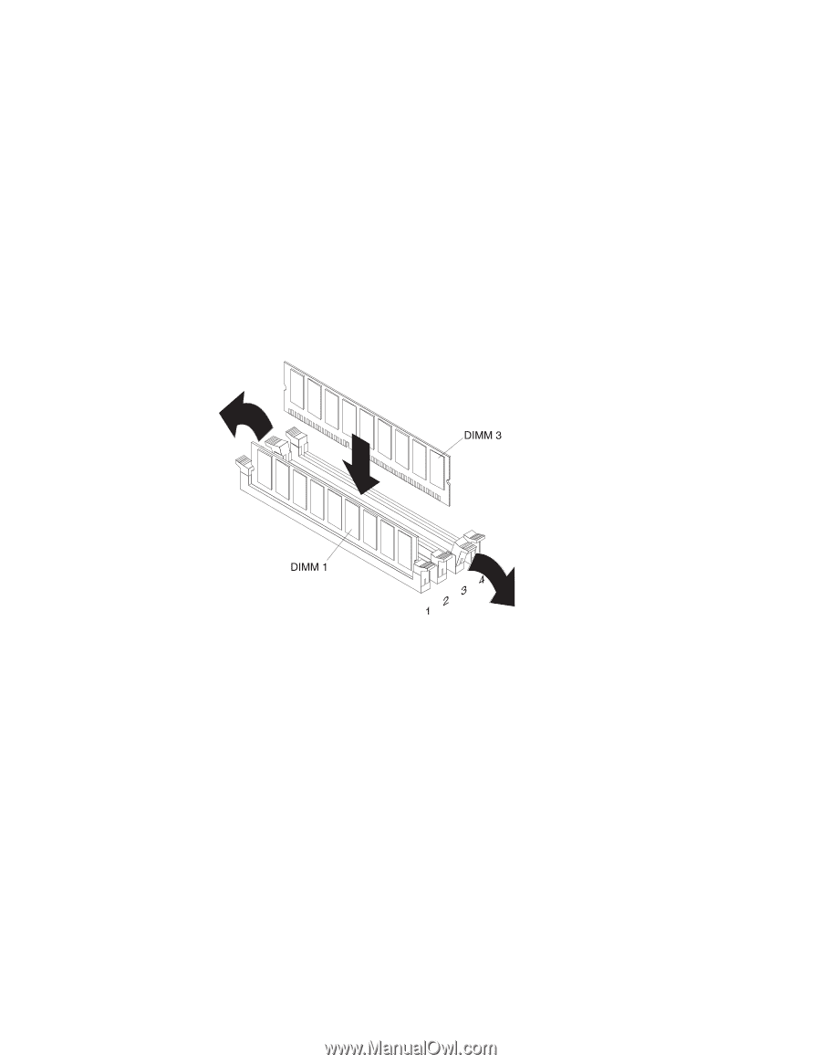
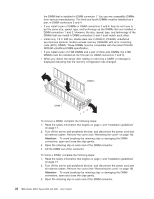
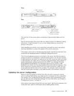
the DIMM that is installed in DIMM connector 1. You can mix compatible DIMMs from various manufacturers. The third and fourth DIMMs must be installed as a pair, in DIMM connectors 2 and 4. v If you install a pair of DIMMs in DIMM connectors 2 and 4, they do not have to be the same size, speed, type, and technology as the DIMMs that are installed in DIMM connectors 1 and 3. However, the size, speed, type, and technology of the DIMMs that you install in DIMM connectors 2 and 4 must match each other. v Install only 1.8 V, 240-pin, double-data-rate II (DDR II), PC4200, unbuffered synchronous dynamic random-access memory (SDRAM) with error correcting code (ECC) DIMMs. These DIMMs must be compatible with the latest PC4200 SDRAM unbuffered DIMM specification. v If you install a pair of 2 GB DIMMs and a pair of other-size DIMMs, the 2 GB DIMMs must be installed as the first pair (in DIMM connectors 1 and 3). v When you restart the server after adding or removing a DIMM, a message is displayed indicating that the memory configuration has changed. To remove a DIMM, complete the following steps: 1. Read the safety information that begins on page v and "Installation guidelines" on page 17. 2. Turn off the server and peripheral devices, and disconnect the power cord and all external cables. Remove the cover (see "Removing the cover" on page 18). Attention: To avoid breaking the retaining clips or damaging the DIMM connectors, open and close the clips gently. 3. Open the retaining clip on each end of the DIMM connector. 4. Lift the DIMM out of the connector. To install a DIMM, complete the following steps: 1. Read the safety information that begins on page v and "Installation guidelines" on page 17. 2. Turn off the server and peripheral devices, and disconnect the power cord and all external cables. Remove the cover (see "Removing the cover" on page 18). Attention: To avoid breaking the retaining clips or damaging the DIMM connectors, open and close the clips gently. 3. Open the retaining clip on each end of the DIMM connector. 26 IBM xSeries 306m Types 8849 and 8491: User's Guide
-
 1
1 -
2
-
3
-
4
-
5
-
6
-
7
-
8
-
9
-
10
-
11
-
12
-
13
-
14
-
15
-
16
-
17
-
18
-
19
-
20
-
21
-
22
-
23
-
24
-
25
-
26
-
27
-
28
-
29
-
30
-
31
-
32
-
 33
33 -
 34
34 -
 35
35 -
 36
36 -
 37
37 -
 38
38 -
 39
39 -
 40
40 -
 41
41 -
 42
42 -
 43
43 -
44
-
45
-
46
-
47
-
48
-
49
-
50
-
51
-
52
-
53
-
54
-
55
-
56
-
57
-
58
-
59
-
60
-
61
-
62
-
63
-
64
-
65
-
66
-
67
-
68
-
69
-
70
-
71
-
72
-
73
-
74
 |
 |