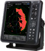
Icom MR-1220 Instruction Manual - Page 25
Advanced measurements, Measuring the distance and direction between two targets
 |
View all Icom MR-1220 manuals
Add to My Manuals
Save this manual to your list of manuals |
Page 25 highlights
3 Distance and direction measurements Advanced measurements DDMeasuring the distance and direction between two targets Using both Electronic Bearing Lines (EBL) and both Variable Range Markers (VRM), the following advanced measurements can be made. 1. Move the cursor onto a target. 2. Push [EBL 1 (VRM 1)]/[ ] to display the EBL 1 and VRM 1 markers. 3. Push [◄] or [►] to rotate the Electronic Bearing Line (EBL), and push [▲] or [▼] to increase or decrease the Variable Range Marker's (VRM) ring size. 4. Push [ENTER]/[ ] to apply the EBL/VRM 1 setting. 5. Move the cursor onto another target. 6. Push [EBL 2 (VRM 2)]/[ ] to display EBL 2 and VRM 2. •• The center of EBL 2/VRM 2 is placed at the intersection of EBL 1 and VRM 1. 7. Push [◄] or [►] to rotate the Electronic Bearing Line (EBL), and push [▲] or [▼] to increase or decrease the Variable Range Marker's (VRM) ring size. 8. The EBL/VRM 2 readout displays the distance between two targets and the direction from the first target to the other. EBL 1/VRM 1 readout EBL 2 marker VRM 2 marker EBL 1 marker VRM 1 marker EBL 2/VRM 2 readout DDMeasuring the relative speed and course of a target 1. Push [TRAIL]/[ ] to turn ON the Trail function, and wait until the set trail time expires. LLThe Trail Time is displayed in the upper left of the screen. 2. Move the cursor onto the end of the trail of a target. 3. Push [EBL 1 (VRM 1)]/[ ] to display the EBL 1 and VRM 1 markers. 4. Push [◄] or [►] to rotate the Electronic Bearing Line (EBL), and push [▲] or [▼] to increase or decrease the Variable Range Marker's (VRM) ring size. 5. Push [ENTER]/[ ] to apply the VRM 1/EBL 1 setting. 6. Push [EBL 2 (VRM 2)]/[ ] to display EBL 2 and VRM 2, and then place them on the current position of the same target. •• The center of EBL 2/VRM 2 is placed at the intersection of EBL 1 and VRM 1. VRM 2 shows the target movement that can be converted into the relative target speed. For example, when the Trail Time is 6 minute, multiplying the distance by ten gives the relative average speed of the target, and the EBL 2 displays the course direction of the target. LLIf your vessel is stationary during the plot time, converted value shows the absolute speed and direction of the target. EBL 1/VRM 1 readout EBL 1 marker VRM 1 marker VRM 2 marker EBL 2 marker EBL 2/VRM 2 readout 1 2 3 4 5 6 7 8 9 10 11 12 13 14 15 16 17 18 19 20 21 20
-
 1
1 -
2
-
3
-
4
-
5
-
6
-
7
-
8
-
9
-
10
-
11
-
12
-
13
-
14
-
15
-
16
-
17
-
18
-
19
-
 20
20 -
 21
21 -
 22
22 -
 23
23 -
 24
24 -
 25
25 -
 26
26 -
 27
27 -
 28
28 -
 29
29 -
 30
30 -
31
-
32
-
33
-
34
-
35
-
36
-
37
-
38
-
39
-
40
-
41
-
42
-
43
-
44
-
45
-
46
-
47
-
48
-
49
-
50
-
51
-
52
-
53
-
54
-
55
-
56
-
57
-
58
-
59
-
60
-
61
-
62
-
63
-
64
-
65
-
66
-
67
-
68
-
69
-
70
-
71
-
72
-
73
-
74
-
75
-
76
-
77
-
78
-
79
-
80
 |
 |
