Icom MR-1220 Instruction Manual - Page 61
Settings for a maintenance, Selecting the language, Simulation mode, Adjusting the heading line
 |
View all Icom MR-1220 manuals
Add to My Manuals
Save this manual to your list of manuals |
Page 61 highlights
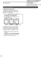
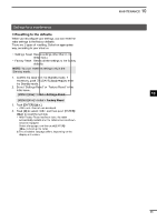
Maintenance 10 Settings for a maintenance DDSelecting the language You can change the displayed language such as the items in the main screen, the Menu screen, and warning messages. LLThe selectable language differs, depending on the display unit version. 1. Select the Language setting the Initial Menu. [MENU]/[ ] > Initial > Language 2. Push [▲] or [▼] to select a language, and then push [ENTER]/[ ] to apply. DDSimulation mode You can boot up the radar in the simulation mode, in such a case you demonstrate the radar functions only with the display unit. 1. Confirm the radar is turned OFF. 2. While holding down [BRILL]/[ ], push [ ] to turn ON the radar. •• The radar boots up in the Simulation Mode. •• After the radar boots up, "Simulation Mode" blinks at the top of the screen. 3. Push [TX (SAVE)]/[ ] to simulate the PPI screen. NOTE: To return to the normal operation, turn OFF the radar, and then Turn it ON again. DDAdjusting the heading line 1 If the heading marker line differs from the actual bow direction, in such a case the scanner has not been 2 mounted correctly in the line with the bow, you can adjust the "Heading Adjust" setting in the Initial menu. 3 1. Line up the bow of the ship with a fixed target. 4 2. Select the Heading Adjust setting the Initial Menu. [MENU]/[ ] > Initial > Heading Adjust 5 3. Push [▲] or [▼] to adjust the heading until the 6 target on the screen meets the heading marker. (The difference can be readout on the screen.) 7 8 Difference 9 10 11 12 13 4. Push [ENTER]/[ ] to apply. 14 DDSetting the antenna height 15 After mounting the scanner unit, properly set the "Antenna Height" in the Video Menu. 16 1. Select the Antenna Height setting the Video Menu. 17 [MENU]/[ ] > Video > Antenna Height 18 2. Push [▲] or [▼] to select the height from the water surface to the antenna, and then push [ENTER]/ [ ] to apply. 19 20 21 56
-
 1
1 -
2
-
3
-
4
-
5
-
6
-
7
-
8
-
9
-
10
-
11
-
12
-
13
-
14
-
15
-
16
-
17
-
18
-
19
-
20
-
21
-
22
-
23
-
24
-
25
-
26
-
27
-
28
-
29
-
30
-
31
-
32
-
33
-
34
-
35
-
36
-
37
-
38
-
39
-
40
-
41
-
42
-
43
-
44
-
45
-
46
-
47
-
48
-
49
-
50
-
51
-
52
-
53
-
54
-
55
-
 56
56 -
 57
57 -
 58
58 -
 59
59 -
 60
60 -
 61
61 -
 62
62 -
 63
63 -
 64
64 -
 65
65 -
 66
66 -
67
-
68
-
69
-
70
-
71
-
72
-
73
-
74
-
75
-
76
-
77
-
78
-
79
-
80
 |
 |
