Intel D865GLC Manual
Intel D865GLC - Desktop Board Motherboard Manual
 |
UPC - 683728198374
View all Intel D865GLC manuals
Add to My Manuals
Save this manual to your list of manuals |
Intel D865GLC manual content summary:
- Intel D865GLC | Manual - Page 1
D865GLC Motherboard Manual ® . . C O M P U T E R S N E T W O R K S S O L U T I O N S G r e a t Minds T h i n k ® - Intel D865GLC | Manual - Page 2
Install the system according to Viglen's instructions >If you open up your Viglen: standards for use in residential and light industrial areas-this specifies a 10 item. If you still experience problems, contact Viglen's Technical Support department who will put you D865GLC Motherboard Manual 1 - Intel D865GLC | Manual - Page 3
, Windows 95,Windows 98, Windows ME, Windows 2000 Pro, Windows XP Pro and MS-DOS are registered trademarks of Microsoft Corporation. IBM PC, XT, AT and PS/2 are trademarks of International Business Machines Corporation. Pentium and Pentium Pro are registered trademarks of Intel Corporation. AMI BIOS - Intel D865GLC | Manual - Page 4
Back Panel Connectors Feature Summary System Processor System Memory Memory Configurations Intel 865G Chipset Intel 865G Graphics Subsystem USB Support IDE Support Real-Time Clock, CMOS SRAM and Battery I/O Controller Audio Subsystem Audio Connectors LAN Subsystem Hardware Management Subsystem Power - Intel D865GLC | Manual - Page 5
51 Intel/AMI BIOS 52 Configuring the Motherboard using BIOS Setup 58 Setting the Processor Speed 59 Clearing the Passwords 60 BIOS Setup Program 61 Maintenance Menu 62 Main Menu 62 Advanced Menu 64 Security Menu 79 Power Menu 81 Boot Menu 83 Exit Menu 88 Upgrading the BIOS - Intel D865GLC | Manual - Page 6
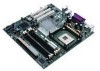
This manual describes the Viglen D865GLC motherboard inside your computer. The motherboard is the most important part of your computer. It contains all of the CPU, memory and graphics circuitry that make the computer work. The motherboard contains the very latest CPU design, the Intel Pentium - Intel D865GLC | Manual - Page 7
jumper block W Aux front panel power LED connector X Front panel connector Y Serial ATA connectors Z Front panel USB connectors AA Intel 82801EB I/O Controller Hub (ICH5) BB Front Panel USB connector CC Battery DD PCI bus add-in card connectors EE Aux line-in connector D865GLC Motherboard Manual - Intel D865GLC | Manual - Page 8
PS/2 keyboard and mouse connectors as well as one serial port, one parallel port, two USB ports, one LAN Port and the audio connectors. Figure 2: Rear I/O Shield Note: Power to the computer should be turned off before a keyboard or mouse is connected or disconnected. D865GLC Motherboard Manual 7 - Intel D865GLC | Manual - Page 9
cache - Socket micro PGA 478 connector - Four 184-pin DDR SDRAM Dual Inline DIMM sockets. - Support for up to 4GB of DDR266, DDR333 or DDR400 SRAM DIMMs using 2.5V memory Intel 865G Chipset - Intel® 82865G Graphics and Memory Controller Hub (GMCH) - Intel® 82801EB I/O Controller Hub (ICH5) - 4 Mbit - Intel D865GLC | Manual - Page 10
4GB. The BIOS automatically detects memory type, size, and speed. The motherboard supports the following memory features: • 2.5 V (only) 184-pin DDR SDRAM DIMMs with gold-plated contacts • Unbuffered, single-sided or double-sided DIMMs with the following restriction: D865GLC Motherboard Manual 9 - Intel D865GLC | Manual - Page 11
compliant with all applicable DDR SDRAM memory specifications, the board should be populated with DIMMs that support the Serial Presence Detect (SPD) data structure. This allows the BIOS to read the SPD data and program the chipset to accurately configure memory settings for optimum performance. If - Intel D865GLC | Manual - Page 12
with Dynamic Single DIMM or DIMMs matched with a channel Mode (Example configurations are shown in Figure 6) Single Channel without Dynamic DIMMs not matched Lowest Mode (Example configurations are shown in Figure 7) Figure 3: Memory Channel Configurations D865GLC Motherboard Manual 11 - Intel D865GLC | Manual - Page 13
) Figure 4: Examples of Dual Channel configurations with Dynamic Mode Dual Channel Configuration without Dynamic Mode - DIMMs not matched within channel - DIMMs match Channel A to Channel B Figure 5: Examples of Dual Channel Configurations without Dynamic mode D865GLC Motherboard Manual 12 - Intel D865GLC | Manual - Page 14
Single Channel Configurations with Dynamic Mode (Single DIMM or DIMMs matched within channel) Figure 6: Examples of Single Channel Configurations with Dynamic mode Single Channel Configurations without Dynamic Mode (DIMMs not matched) D865GLC Motherboard Manual 13 - Intel D865GLC | Manual - Page 15
in Setup, some performance loss occurs. Table 5: Memory Type Memory Error Detection Mode Established in Setup Program Non-ECC DIMM ECC DIMM ECC Disabled No error detection No error detection ECC Enabled N/A Single-bit error correction, multiple-bit error detection D865GLC Motherboard Manual 14 - Intel D865GLC | Manual - Page 16
Hub Architecture interface. The ICH5 is a centralised controller for the board's I/O paths. The FWH provides the nonvolatile storage of the BIOS. The component combination provides the chipset interfaces as shown in Figure 8. Figure 8: Intel 865G Chipset Block Diagram D865GLC Motherboard Manual 15 - Intel D865GLC | Manual - Page 17
clocks using an AGP Digital Display (ADD) card • Dynamic Video Memory Technology (DVMT) support up to 64 MB (driver dependent) • Intel 865G Chipset o 400/533/800 MHz Front Side Bus (FSB) o AGP 8x 1.5volt Table 6: Supported Graphics Modes using an Analog CRT Resolution Max Colour palette Max - Intel D865GLC | Manual - Page 18
operating system and graphics drivers allocate additional system memory to the graphics buffer as needed for performing graphics functions. Note: The use of DVMT requires operating system driver support Zone Rendering Technology (ZRT) The Intel Extreme Graphics 2 Controller supports Zone Rendering - Intel D865GLC | Manual - Page 19
are each capable of driving a 165 MHz pixel clock to the AGP connector. The DVO ports can be paired for dual channel mode. In dual channel mode, the GMCH is capable of driving a 24-bit 330 MHz pixel clock. When an AGP add-in card is used, the Intel Extreme Graphics 2 D865GLC Motherboard Manual 18 - Intel D865GLC | Manual - Page 20
is disabled and the AGP connector operates in AGP mode. When an ADD card is detected, the Intel Extreme Graphics 2 controller is enabled and the AGP connector is configured for DVO mode. DVO mode enables the DVO ports to be accessed by an ADD card. ADD cards can support up to two display devices - Intel D865GLC | Manual - Page 21
to the PS/2 connectors • Two ports are implemented with stacked back panel connectors, adjacent to the audio connectors • Four ports are routed to two separate front panel USB connectors Note: USB 2.0 drivers are available for Windows 2000 Pro and Windows XP, and currently not supported by any other - Intel D865GLC | Manual - Page 22
formatted diskette and is supported by Windows 95 and Windows NT operating system. The D865GLC board allows connection of an LS-120 compatible drive and a standard 3½" floppy drive. The LS-120 drive can be configured as a boot device before a floppy drive, if selected in the BIOS setup utility. Note - Intel D865GLC | Manual - Page 23
fan tachometer inputs • Integrated USB hub By default, the I/O controller interfaces are automatically configured during boot up. The I/O controller can also be manually configured in the Setup program. Serial Ports One 9-pin D-Sub serial port connector is located on the back panel and is compatible - Intel D865GLC | Manual - Page 24
in Setup. The keyboard controller also supports the hot-key sequence for a software reset. This key sequence resets the computer's software by jumping to the beginning of the BIOS code and running the Power-On Self Test (POST). Audio Subsystem The D865GLC motherboard provides a Flex - Intel D865GLC | Manual - Page 25
below: Figure 9: Back Panel Audio Connector Options Note: To access the S/PDIF signal with the 5.1 Digital Shared Jack option, connect a 1/8-inch stereo phone plug to RCA jack adapter/splitter as shown in Figure 10. Figure 10: Adapter for S/PDIF Back Panel Connector D865GLC Motherboard Manual 24 - Intel D865GLC | Manual - Page 26
In Connector A 1 x 4-pin ATAPI-style connector connects the left and right channel signals of an internal audio device to the audio subsystem. ATAPI CDROM Audio Connector A 1 x 4-pin ATAPI-style connector connects an internal ATAPI CD-ROM drive to the audio mixer. D865GLC Motherboard Manual 25 - Intel D865GLC | Manual - Page 27
via the CNR connector. The Intel 82562EZ provides the following functions: • Basic 10/100 Ethernet LAN Connectivity • Supports RJ-45 connector with status indicator LEDs • Full driver compatibility • Advanced Power Management support • Programmable transit threshold • Configuration EEPROM that - Intel D865GLC | Manual - Page 28
or below acceptable values • Thermally monitored closed-loop fan control, for all three fans, that can adjust the fan speed or switch the fans on or off as needed • SMBus interface Thermal Monitoring Figure 11 shows the location of the sensors and fan connectors. D865GLC Motherboard Manual 27 - Intel D865GLC | Manual - Page 29
direct control over the power management and Plug and Play functions of a computer. The use of ACPI with the D865GLC motherboard requires an operating system that provides full ACPI support. ACPI features include: • Plug and Play (including bus and device enumeration) D865GLC Motherboard Manual 28 - Intel D865GLC | Manual - Page 30
driver), video displays, and hard disk drives • Methods for achieving less than 15-watt system operation in the poweron/standby sleeping state • A Soft-off feature that enables the operating system to power-off the computer • Support for multiple wake-up events • Support for a front panel power - Intel D865GLC | Manual - Page 31
of standby current required depends on the wake devices supported and manufacturing options. The D865GLC motherboard provides several power management hardware features, including: • Power connector • Fan connectors • LAN wake capabilities • Instantly Available PC technology • Resume on Ring - Intel D865GLC | Manual - Page 32
Power State feature in the BIOS Setup program's Boot menu. LAN wake Capabilities CAUTION! For LAN wake capabilities, the +5 V standby line for the power the LAN subsystem asserts a wake-up signal that powers up the computer. Depending on the LAN implementation, the D865GLC motherboard supports LAN - Intel D865GLC | Manual - Page 33
USB. Wake from PS/2 Devices PS/2 device activity wakes the computer from an ACPI S1 or S3 state. PME# Signal Wake-up Support When the PME# signal on the PCI bus is asserted, the computer wakes from an ACPI S1, S3, S4, or S5 state (with Wake on PME enabled in BIOS). D865GLC Motherboard Manual 32 - Intel D865GLC | Manual - Page 34
Chapter 2: System Board Options The D865GLC motherboard is capable of accepting Pentium 4 CPU's. RAM can be upgraded to a maximum of 4GB using DDR266, DDR333 or DDR400 SDRAM DIMMs ECC and Non ECC 2.5volt Unbuffered memory. WARNING! Unplug the system before carrying out the procedures described in - Intel D865GLC | Manual - Page 35
: We recommend that you return your computer to the service department for upgrading. Any work carried out is fully guaranteed. Upgrades should only be carried out by persons who are familiar with handling IC's, as incorrect installation will invalidate the guarantee. D865GLC Motherboard Manual 34 - Intel D865GLC | Manual - Page 36
The D865GLC motherboard contains the latest technology to offer an almost jumperless configuration. All Pentium 4 CPUs are automatically detected and the Speed is automatically set from the information provided by the CPU. The only jumper present on the motherboard is for clearing all the CMOS - Intel D865GLC | Manual - Page 37
header on the motherboard. The audio jumper block (J9A2) allows the implementation of front panel audio. J9A2 Intel 865G Chipset ` PGA 478 Socket J9J4 Figure 12: Single-Jumper Configurations Table 11: Configuration Jumper Settings Function Jumper Configuration J9J4 Normal 1-2 The BIOS uses - Intel D865GLC | Manual - Page 38
12: Front Panel Audio Jumper Settings Function Jumper Configuration J9A2 Normal 5 - 6 The audio line signals are routed back to the line connector. and 9- 10 Front audio cable none Audio line out and mic in signals are available for front panel audio connectors on this connector when no - Intel D865GLC | Manual - Page 39
chassis 1 1 1 2 Front USB Header 7 10 1 2 Front USB Header 7 10 Serial ATA Header 0& 1 1 2 Intel 865G Chipset ` 8 9 Front Panel Connectors 1 Configuration Jumper 1 Chassis Intrusion 1 FAN Front Chassis PSU ATX 12V PGA 478 Socket 1 CPU FAN 20 11 10 Power Connector 1 2 31 - Intel D865GLC | Manual - Page 40
pins are shorted, it will cause the computer to perform a cold reboot. C - Power L.E.D. This attaches to the power L.E.D on the front panel, to display if the computer is active or not. D- Power On/Off When these pins are shorted it turns the computer on and off. D865GLC Motherboard Manual 39 - Intel D865GLC | Manual - Page 41
) 5. Lift arm on Socket to release the CPU 6. Lift the CPU Vertically upwards until it is clear of the socket You can now fit the replacement CPU and heat sink into the socket. Figure 15: Installing the CPU heatsink (note heatsink type may vary from one shown above) D865GLC Motherboard Manual 40 - Intel D865GLC | Manual - Page 42
ECC Configuration feature in Setup to enable the use of ECC. Removing Memory To remove a DIMM, follow these steps: 1. Observe the precautions in "Before You Begin". 2. Turn off all peripheral devices connected to the computer. Turn off the computer. 3. Remove the computer cover. D865GLC Motherboard - Intel D865GLC | Manual - Page 43
socket, and store it in an antistatic package. 5. Reinstall and reconnect any parts you removed or disconnected to reach the DIMM sockets. Figure 16: Removing Memory Modules D865GLC Motherboard Manual 42 - Intel D865GLC | Manual - Page 44
according to manufacturer's instructions. The battery is listed as board component 'CC' free from its socket, taking care to note the "+" and "-" orientation of the battery (Figure 17). 6. Install the new battery in the socket. + + 1 2 Figure 17: Removing the Battery D865GLC Motherboard Manual - Intel D865GLC | Manual - Page 45
: Clear the system memory and reload the operating system (also called warm reset). Cold boot: Clear the system memory, halt Power off/on or reset button (at front power to all peripherals, restart POST, and of the system) reload the operating system. D865GLC Motherboard Manual - Intel D865GLC | Manual - Page 46
Errors that prevent the boot process from continuing (fatal errors), are communicated by a series of audible beeps. If this type of error occurs, refer to the error codes and messages listed at the end of this chapter. 6. Confirm that the operating system has loaded. D865GLC Motherboard Manual 45 - Intel D865GLC | Manual - Page 47
contact the board vendor's customer service representative. Did you install the add-in board according to the manufacturer's instructions? Check the documentation that came with the board. Are all cables installed properly? The following items are suggestions for troubleshooting problems related to - Intel D865GLC | Manual - Page 48
the settings. Replace the battery (Chapter 2). Diskette drive light does not go on when drive is in use or is tested by POST Make sure the power and signal cables for the drive are properly installed. Check that the drive is properly configured and enabled in Setup. D865GLC Motherboard Manual 47 - Intel D865GLC | Manual - Page 49
installed. Make sure the front panel connector is securely attached to the system board headers. Check that the drive is properly configured and enabled in Setup. Check the drive manufacturer's manual for proper configuration for remote hard disk drive activity. Power-on light does not go on If - Intel D865GLC | Manual - Page 50
test failed. Memory Size Decreased Memory size has decreased since the last boot. If no memory was removed then memory may be bad. Memory Size Increased Memory size has increased since the last boot. If no memory was added there may be a problem with the system. D865GLC Motherboard Manual 49 - Intel D865GLC | Manual - Page 51
occurred in onboard memory at an unknown address. NVRAM/CMOS/PASSWOR NVRAM, CMOS, and passwords have been cleared. The system D cleared by Jumper should be powered down and the jumper removed. Pressed CMOS is ignored and NVRAM is cleared. User must enter Setup. BIOS Beep Codes If an - Intel D865GLC | Manual - Page 52
the boot password to continue. The following section describes how to do this. The BIOS then loads the operating system, either - MS DOS, Windows 98SE, OS/2 or NetWare, etc. - from the hard disk (or floppy disk if one is inserted in Drive A:). The computer is then ready for use. D865GLC Motherboard - Intel D865GLC | Manual - Page 53
auto-configuration utility, and is Windows 95-ready Plug and Play. This motherboard supports system BIOS shadowing, allowing the BIOS to execute from 64-bit onboard write-protected DRAM. The BIOS displays a message during POST identifying the type of BIOS and the revision code. BIOS Upgrades A new - Intel D865GLC | Manual - Page 54
and performance. To take advantage of the high-capacity storage devices, hard drives are automatically configured for logical block addressing (LBA) and to PIO Mode 3 or 4, depending on the capability of the drive. To override the auto-configuration options, use the D865GLC Motherboard Manual 53 - Intel D865GLC | Manual - Page 55
service-level application running on a non-Plug and Play OS can access the DMI BIOS information. Advanced Power Management (APM) The BIOS supports APM and standby mode. The energy saving standby mode can be initiated in the following ways: • Time-out period specified in Setup. D865GLC Motherboard - Intel D865GLC | Manual - Page 56
restores power to the monitor. The BIOS enables APM by default, but the operating system must support an APM driver for the power-management features to work. For example, Windows 95 supports the power-management features upon detecting that APM is enabled in the BIOS. D865GLC Motherboard Manual - Intel D865GLC | Manual - Page 57
enables the operating system to power off the computer. • Support for multiple wake up events. • Support for a front panel power and sleep mode switch. Table 19 describes the system states based on how long the power switch is pressed, depending on how ACPI is configured with an ACPI-aware operating - Intel D865GLC | Manual - Page 58
. Recovering BIOS Data Some types of failure can destroy the BIOS. For example, the data can be lost if a power outage occurs while the BIOS is being updated in flash memory. The BIOS can be recovered from a diskette with recovery files using the BIOS recovery mode. D865GLC Motherboard Manual 57 - Intel D865GLC | Manual - Page 59
result in personal injury or equipment damage. Some circuitry on the motherboard may continue to operate even though the front panel power button is off. CAUTION! Electrostatic discharge (ESD) can damage strap and attaching it to a metal part of the computer chassis. D865GLC Motherboard Manual 58 - Intel D865GLC | Manual - Page 60
. 13. On the header (J9J4), move the jumper back to pins 1-2 to restore normal operation as shown below. 1 2 3 Configuration Jumper J9J4 14. Replace the cover and turn on the computer. 15. Verify the processor speed in the start-up information the BIOS displays. D865GLC Motherboard Manual 59 - Intel D865GLC | Manual - Page 61
Replace the cover and turn on the computer. The Setup program is for viewing and changing the BIOS settings for a computer. Setup is accessed by pressing the key after the Power-On Self Test (POST) memory test begins and before the operating system boot begins. D865GLC Motherboard Manual 60 - Intel D865GLC | Manual - Page 62
left or right) Selects an item (Moves the cursor up or down) Selects a field (Not implemented) Executes command or selects the submenu Load the default configuration values for the current menu Save the current values and exits the BIOS Setup program Exits the menu D865GLC Motherboard Manual 61 - Intel D865GLC | Manual - Page 63
mode "Jumper (J9J4) set across pins 1 and 2" the main menu will appear as below after selecting during power on boot up when the text press is displayed. This menu reports processor and memory information and is for configuring the system date, system time. D865GLC Motherboard Manual 62 - Intel D865GLC | Manual - Page 64
the CPU Front Side Bus speed Displays the system memory speed Displays size of second-level cache. Displays the total amount of RAM on the motherboard. Displays the memory mode (Dual Channel or Single Channel) Specifies the current time. Specifies the current date. D865GLC Motherboard Manual 63 - Intel D865GLC | Manual - Page 65
devices Specifies type on connected IDE devices Configures the diskette drive Configures Event Logging Configures video features Configure USB support Configures advanced chipset features Configures fan operation Monitors system temperatures, voltages and fan speeds D865GLC Motherboard Manual 64 - Intel D865GLC | Manual - Page 66
is for configuring the PCI peripherals. Advanced BIOS SETUP UTILITY PCI Configuration PCI Slot1 IRQ selection of IRQ priority for PCI bus connector 1 Allows selection of IRQ priority for PCI bus connector 2 Allows selection of IRQ priority for PCI bus connector 3 D865GLC Motherboard Manual 65 - Intel D865GLC | Manual - Page 67
and Play operating system. Yes lets the operating system configure Plug and Play devices not required to boot the system. This option is available for use during lab testing. Specifies the power-on state of the numlock feature on the numeric keypad of the keyboard. D865GLC Motherboard Manual 66 - Intel D865GLC | Manual - Page 68
is for configuring the computer peripherals. Advanced BIOS SETUP UTILITY Peripheral Configuration Serial Port A Parallel Port Mode [Auto] [Auto] [Bi-directional] Audio Device Onboard LAN [Enabled] interrupt for serial port A, if serial port A is set to Enabled. D865GLC Motherboard Manual 67 - Intel D865GLC | Manual - Page 69
when Parallel Port Mode is set to ECP) Audio • Enabled (default) • Disabled Onboard LAN • Enabled (default) • Disabled Configures the parallel port. Auto assigns LPT1 the address disables the onboard audio subsystem Enables or disables the onboard LAN device D865GLC Motherboard Manual 68 - Intel D865GLC | Manual - Page 70
ATA SATA = Serial ATA Pri = Primary Sec = Secondary P0 = Serial ATA Connector 0 P1 = Serial ATA connector 1 This feature is present only when the ATA/IDE configuration option is set to legacy Enables/disables the use of DMA for hard drive BIOS INT13 reads and writes D865GLC Motherboard Manual 69 - Intel D865GLC | Manual - Page 71
Type is set to User) Displays whether automatic multiple sector data transfers are enabled (This item is read-only unless Type is set to User) D865GLC Motherboard Manual 70 - Intel D865GLC | Manual - Page 72
[Enabled] [1.44/1.25 MB 3½"] [Disable] Configures the integrated diskette controller ←→ ↑↓ Tab Enter F1 F9 F10 ESC Select Menu Select Item Select Field Select sub-menu General Help Setup Defaults Save and Exit Exit Figure 25: Diskette Configuration Submenu D865GLC Motherboard Manual 71 - Intel D865GLC | Manual - Page 73
event log Clear event log Event Logging [Enter] • Ok (default) • Cancel • Disabled • Enabled (default) Description Indicates if there is space available in the event log. Displays the event log Clears the DMI Event Log after rebooting. Enables logging of DMI events. D865GLC Motherboard Manual 72 - Intel D865GLC | Manual - Page 74
16 MB (default) Description Sets the aperture size for the video controller Selects primary video adapter to be used during boot Controls how much system RAM is reserved for use by the internal graphics device. A larger frame buffer should provide higher performance. D865GLC Motherboard Manual 73 - Intel D865GLC | Manual - Page 75
Legacy Support • Enabled (default) • Disabled • FullSpeed (default) • Hi Speed Description Set to Disabled when a USB 2.0 driver is not available Enables/disables legacy USB support. Configures the USB 2.0 Legacy support to Hi Speed (480 Mbps) or Full Speed (12 Mbps) D865GLC Motherboard Manual - Intel D865GLC | Manual - Page 76
values may cause your system to malfunction. ISA Enable Bit PCI Latency timer [Enabled] [32] 8Burn-In Mode Extended Configuration [Default] Chipset Memory Timing Control SDRAM Frequency [Auto] CPC Override [Auto] SDRAM Timing Control [Auto] SDRAM RAS Act. To Pre. [7] SDRAM CAS - Intel D865GLC | Manual - Page 77
memory. Selects the number of clock cycles between addressing a row and addressing a column. Selects the length of time required before accessing a new row. Note: 1. This feature is displayed only if Extended Configuration Control is set to Manual - User Defined. D865GLC Motherboard Manual 76 - Intel D865GLC | Manual - Page 78
options will not take effect until power has been completely removed from the system. After saving the BIOS settings and turning off the system, unplug the power cord from the system and wait at least 30 seconds before reapplying power and turning the system back on. D865GLC Motherboard Manual 77 - Intel D865GLC | Manual - Page 79
↑↓ ] Tab Select Item Select Field Enter Select sub-menu F1 General Help F9 Setup Defaults F10 Save and Exit ESC Exit Figure 31: Hardware Monitoring D865GLC Motherboard Manual 78 - Intel D865GLC | Manual - Page 80
Advanced BIOS SETUP UTILITY Security Power Boot BIOS Setup Utility. View Only allows the user to view but not change the BIOS Setup Utility fields. Limited allows the user to changes some fields. Full allows the user to changes all fields except the supervisor password. D865GLC Motherboard Manual - Intel D865GLC | Manual - Page 81
"Clear Chassis Intrusion Status" to clear the Chassis intrusion flag. Note: 1. Valid password characters are A-Z, a-z, and 0-9. 2. This feature is displayed only if a supervisor password has been set. 3. This feature is displayed only if a user password has been set. D865GLC Motherboard Manual - Intel D865GLC | Manual - Page 82
features. Main Advanced Security BIOS Setup Utility Power Boot Exit Advanced Configuration and Power Interface ACPI Suspend State Wake on LAN from S5 [S3 State] [Stay Off] S1 is the safest mode But consumes more power. S3 consumes low power but drivers may not support this state. ←→ ↑↓ Tab - Intel D865GLC | Manual - Page 83
Wake on LAN from S5 • Stay off (default) • Power on Description S1 is the safest mode but consumes more power. S3 consumes less power, but some drivers may not support this state. In ACPI soft-off mode only, determines how the system responds to a LAN wake-up event. D865GLC Motherboard Manual 82 - Intel D865GLC | Manual - Page 84
displays OEM graphic instead of POST messages. Enables the computer to boot without running certain POST tests. Disables/enables PXE boot to LAN. Note: When set to Enabled, you must reboot for the Intel Boot Agent device to be available in the Boot Device menu. D865GLC Motherboard Manual 83 - Intel D865GLC | Manual - Page 85
here. Only one of the devices can be an IDE hard disk drive. To specify boot sequence: 1. Select the boot device 2. Press to set the selection as the intended boot device. The default settings for the first through fourth boot devices are, respectively: D865GLC Motherboard Manual 84 - Intel D865GLC | Manual - Page 86
> to set the selection as the intended boot device. Note: This boot device submenu appears only if at least one boot device of this type is installed. This list will display up to twelve hard disk drives, the maximum number of hard disk drives supported by the BIOS. D865GLC Motherboard Manual 85 - Intel D865GLC | Manual - Page 87
> to set the selection as the intended boot device. Note: This boot device submenu appears only if at least one boot device of this type is installed. This list will display up to four removable devices, the maximum number of removable devices supported by the BIOS. D865GLC Motherboard Manual 86 - Intel D865GLC | Manual - Page 88
set the selection as the intended boot device. Note: This boot device submenu appears only if at least one boot device of this type is installed. This list will display up to four ATAPI CD-ROM drives, the maximum number of ATAPI CD-ROM drives supported by the BIOS. D865GLC Motherboard Manual 87 - Intel D865GLC | Manual - Page 89
changes in CMOS RAM. memory. If this memory is corrupted, the BIOS reads the custom defaults. If no custom defaults are set, the BIOS reads the factory defaults. Discards changes without exiting Setup. The option values present when the computer was turned on are used. D865GLC Motherboard Manual - Intel D865GLC | Manual - Page 90
computer supplier or from the Intel World Wide Web site: http://www.viglen.co.uk Note: Please review the instructions distributed with the upgrade utility before attempting a BIOS upgrade. This upgrade utility allows you to: • Upgrade the BIOS in flash memory. • Update the language section of the - Intel D865GLC | Manual - Page 91
Upgrading the BIOS 1. Boot the computer with the floppy disk in drive A. The BIOS upgrade utility screen appears. 2. Select Update Flash Memory From a File. 3. Select Update System BIOS. Press . 4. Use the arrow keys to select the correct .bio file. Press . D865GLC Motherboard Manual - Intel D865GLC | Manual - Page 92
. Turn off the computer. 2. Remove the computer cover. 3. Locate the configuration header (Jumper J9J4 on the motherboard). 4. On the header (J9J4), remove the jumper from all pins as shown below to set recovery mode for Setup. 1 2 3 Configuration Jumper J9J4 D865GLC Motherboard Manual 91 - Intel D865GLC | Manual - Page 93
the jumper back to pins 1-2 as shown below to set normal mode for Setup. 1 2 3 Configuration Jumper J9J4 12. Replace the computer cover and reconnect the AC power cable; leave the upgrade disk in drive A and turn on the computer. 13. Continue with the BIOS upgrade. D865GLC Motherboard Manual 92 - Intel D865GLC | Manual - Page 94
drive used. Logical Block mode overcomes the 528MB maximum size limitation imposed by the Standard CHS mode. It should be used only when the drive supports LBA (Logical Block Addressing), and the OS supports LBA, or uses the BIOS to access the disk. D865GLC Motherboard Manual 93 - Intel D865GLC | Manual - Page 95
combination will also provide the best performance. If this driver is not installed and the drive fitted to the system supports Type F DMA on the ISA interface or Mode 3 on the PCI interface then higher performance will be achieved by NOT using '32-bit Disk Access'. D865GLC Motherboard Manual 94 - Intel D865GLC | Manual - Page 96
4 CD_IN-Right Table 51: Chassis Intrusion Connector Pin Signal Name 1 Ground 2 CHS_SEC Table 52: Fan 2 Connector Pin Signal Name 1 Ground 2 FAN_CTRL (+12 V) 3 FAN_SEN* * If the optional management extension hardware is not available, pin 3 is ground. D865GLC Motherboard Manual 95 - Intel D865GLC | Manual - Page 97
Table 54: SCSI LED Header Pin Signal Name 1 DRV_ACT# 2 No connect Table 55: Serial ATA Connector Pin Signal Name 1 Ground 25 Ground 26 27 Connect 28 29 Ground 30 31 Ground 32 33 Ground 34 Signal Name DENSEL Reserved FDEDIN FDINDX# (Index) D865GLC Motherboard Manual 96 - Intel D865GLC | Manual - Page 98
) 29 DDACK0# [DDACK1#] 30 Ground 31 IRQ 14 [IRQ 15] 32 Reserved 33 Address 1 34 Reserved 35 Address 0 36 Address 2 37 in brackets ([ ]) are for the secondary IDE connector. Table 58: Accelerated Graphics Port Pin Signal Name Pin Signal Pin Name A1 D865GLC Motherboard Manual 97 - Intel D865GLC | Manual - Page 99
14 PS-ON# (power supply remote on/off control) 15 Ground 16 Ground 17 Ground 18 -5 V 19 +5 V 20 +5 V Table 60: Front Panel I/O Connectors Connector Pin Signal Name Sleep/Power 2 +5 V LED Green Sleep/Power 4 0v LED Yellow Power Switch 6 SWITCH ON Power Switch 8 Ground No - Intel D865GLC | Manual - Page 100
Tip Audio Left Out Ring Audio Right Out Table 65: Audio Line In Connector Pin Signal Name Sleeve Ground Tip Audio Left In Ring Audio Right In Table 66: Audio Mic In Connector Pin Signal Name Sleeve Ground Tip Mono In Ring Electret Bias Voltage D865GLC Motherboard Manual 99 - Intel D865GLC | Manual - Page 101
Table 67: Parallel Port Connector Pin Signal Name 1 Strobe# 2 Data bit 0 3 Data bit 1 4 Data bit 2 5 Data bit 3 6 Data bit 4 7 Data bit 5 8 Data bit 6 9 Data bit 7 10 ACK# 11 Busy 12 A51 Key B51 Key A21 +3.3 V B21 AD29 A52 C/BE0# B52 AD08 D865GLC Motherboard Manual 100 - Intel D865GLC | Manual - Page 102
configuration registers Counter/Timer 1 Counter/Timer 2 Keyboard Controller Byte NMI, Speaker Control Keyboard controller Real time clock controller DMA page registers Interrupt controller 2 APM control DMA 2 Numeric processor Secondary IDE controller Primary IDE controller D865GLC Motherboard - Intel D865GLC | Manual - Page 103
Resource NMI I/O channel check 0 Reserved, interval timer 1 Reserved, keyboard buffer full 2 Reserved, cascade interrupt from slave PIC 3 COM2* 4 COM1* 5 LPT2 (Plug and Play option) / audio / user available 6 Floppy drive 7 LPT1* 8 Real time clock D865GLC Motherboard Manual 102 - Intel D865GLC | Manual - Page 104
9 Reserved 10 User available 11 Windows Sound System* / user available 12 Onboard mouse port (if present the motherboard is 112,977. 7547 hours. Temperature Table 75: Temperature Temperature Non-operating Operating Specification -40°C to +70°C 0°C to +55°C D865GLC Motherboard Manual 103 - Intel D865GLC | Manual - Page 105
the instructions for the keyboard, disk drives etc., and the VGA BIOS controls the VGA graphics card. CPU Central Processing Unit. This is the main piece of equipment on the motherboard. The CPU processes data, tells memory what to store and the video card what to display. Default The configuration - Intel D865GLC | Manual - Page 106
shadow memory. The System BIOS is responsible for this copying. Super VGA Additional screen modes and capabilities provided over and above the standard VGA defined by IBM. VGA Video Graphics Array - the graphics standard defined by IBM and provided on IBM's PS/2 machines. D865GLC Motherboard Manual - Intel D865GLC | Manual - Page 107
Notes D865GLC Motherboard Manual 106 - Intel D865GLC | Manual - Page 108
keep and improve the standard of their manuals. 1. Is the information provided in this and other manuals clear enough? 2. What could be added to the manual to improve it? 3. Does the manual go into enough detail? 4. Would you like an on-line version of this manual? D865GLC Motherboard Manual 107 - Intel D865GLC | Manual - Page 109
support and Service Departments? 6. Are there any technological improvements that could be made to the system? 7. Other points you would like to mention? Please return this slip to: Product Development Dept. Viglen Ltd. Viglen House Alperton Lane Alperton Middlesex HA0 IDX D865GLC Motherboard
-
 1
1 -
 2
2 -
 3
3 -
 4
4 -
 5
5 -
 6
6 -
 7
7 -
8
-
9
-
10
-
11
-
12
-
13
-
14
-
15
-
16
-
17
-
18
-
19
-
20
-
21
-
22
-
23
-
24
-
25
-
26
-
27
-
28
-
29
-
30
-
31
-
32
-
33
-
34
-
35
-
36
-
37
-
38
-
39
-
40
-
41
-
42
-
43
-
44
-
45
-
46
-
47
-
48
-
49
-
50
-
51
-
52
-
53
-
54
-
55
-
56
-
57
-
58
-
59
-
60
-
61
-
62
-
63
-
64
-
65
-
66
-
67
-
68
-
69
-
70
-
71
-
72
-
73
-
74
-
75
-
76
-
77
-
78
-
79
-
80
-
81
-
82
-
83
-
84
-
85
-
86
-
87
-
88
-
89
-
90
-
91
-
92
-
93
-
94
-
95
-
96
-
97
-
98
-
99
-
100
-
101
-
102
-
103
-
104
-
105
-
106
-
107
-
108
-
109
 |
 |

®
®
C
O
M
P
U
T
E
R
S
N
E
T
W
O
R
K
S
S
O
L
U
T
I
O
N
S
Minds
T h i n k
G r e a t
.
.
D865GLC
Motherboard
Manual