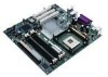
Intel D865GLC Manual - Page 40
Front Panel Connectors - power switch
 |
UPC - 683728198374
View all Intel D865GLC manuals
Add to My Manuals
Save this manual to your list of manuals |
Page 40 highlights
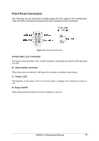
Front Panel Connectors The following are all connectors situated along the front edge of the motherboard. They are often connected to buttons and LED's situated on the front panel. Figure 14: Front panel connectors A- Hard Disk L.E.D. Connector This goes to the Hard Disk L.E.D. on the front panel, which lights up when the IDE Hard Disk is in use. B - Reset switch connector When these pins are shorted, it will cause the computer to perform a cold reboot. C - Power L.E.D. This attaches to the power L.E.D on the front panel, to display if the computer is active or not. D- Power On/Off When these pins are shorted it turns the computer on and off. D865GLC Motherboard Manual 39
-
 1
1 -
2
-
3
-
4
-
5
-
6
-
7
-
8
-
9
-
10
-
11
-
12
-
13
-
14
-
15
-
16
-
17
-
18
-
19
-
20
-
21
-
22
-
23
-
24
-
25
-
26
-
27
-
28
-
29
-
30
-
31
-
32
-
33
-
34
-
 35
35 -
 36
36 -
 37
37 -
 38
38 -
 39
39 -
 40
40 -
 41
41 -
 42
42 -
 43
43 -
 44
44 -
 45
45 -
46
-
47
-
48
-
49
-
50
-
51
-
52
-
53
-
54
-
55
-
56
-
57
-
58
-
59
-
60
-
61
-
62
-
63
-
64
-
65
-
66
-
67
-
68
-
69
-
70
-
71
-
72
-
73
-
74
-
75
-
76
-
77
-
78
-
79
-
80
-
81
-
82
-
83
-
84
-
85
-
86
-
87
-
88
-
89
-
90
-
91
-
92
-
93
-
94
-
95
-
96
-
97
-
98
-
99
-
100
-
101
-
102
-
103
-
104
-
105
-
106
-
107
-
108
-
109
 |
 |

D865GLC Motherboard Manual
39
Front Panel Connectors
The following are all connectors situated along the front edge of the motherboard.
They are often connected to buttons and LED’s situated on the front panel.
Figure 14:
Front panel connectors
A- Hard Disk L.E.D. Connector
This goes to the Hard Disk L.E.D. on the front panel, which lights up when the IDE Hard Disk
is in use.
B - Reset switch connector
When these pins are shorted, it will cause the computer to perform a cold reboot.
C - Power L.E.D.
This attaches to the power L.E.D on the front panel, to display if the computer is active or
not.
D- Power On/Off
When these pins are shorted it turns the computer on and off.