Intel S1200RP Technical Product Specification - Page 87
Power Connectors
 |
View all Intel S1200RP manuals
Add to My Manuals
Save this manual to your list of manuals |
Page 87 highlights
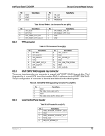
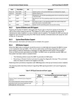
Intel® Server Board S1200V3RP On-board Connector/Header Overview SATA Connector HSBP_I2C SATA SGPIO LCP IPMB Configuration jumpers TPM Chassis Intrusion I/O Module Connector SAS Module Connector Quantity 6 1 1 1 1 5 1 1 1 1 Reference Designators J1K4, J1K1, J1K5, J1K2, J2K5, J2K3 Connector Type Connector J2K4 Header J2K2 Header J1G1 Header J2K1 Header J3K6 (Force Integrated BMC update), J2K9 (Password Clear), J2K8 (BIOS Recovery), J2K6 (Reset BIOS Configuration) J3K2 (ME Firmware Update) Jumper J8J1 Connector J1F1 Header J1C1 Connector J4J1 Connector Pin Count 7 3 5 7 4 3 14 2 80 80 8.2 Power Connectors The main power supply connection uses an SSI-compliant 2x12 pin connector (J9H1). Two additional power-related connectors also exist: One SSI-compliant 2x4 pin power connector (J9B1) to provide 12-V power to the CPU voltage regulators and memory. One SSI-compliant 1x5 pin connector (J9C3) to provide I2C monitoring of the power supply. The following tables define these connector pin-outs: Table 26. Main Power Connector Pin-out (J9H1) Pin Signal 1 +3.3 Vdc 2 +3.3 Vdc 3 GND 4 +5 Vdc 5 GND 6 +5 Vdc 7 GND 8 PWR_OK 9 5 VSB 10 +12 Vdc 11 +12 Vdc 12 +3.3 Vdc Color Orange Orange Black Red Black Red Black Gray Purple Yellow Yellow Orange Pin Signal 13 +3.3 Vdc 14 -12 Vdc 15 GND 16 PS_ON# 17 GND 18 GND 19 GND 20 NC 21 +5 Vdc 22 +5 Vdc 23 +5 Vdc 24 GND Color Orange Blue Black Green Black Black Black White Red Red Red Black Revision 1.0 75
-
 1
1 -
2
-
3
-
4
-
5
-
6
-
7
-
8
-
9
-
10
-
11
-
12
-
13
-
14
-
15
-
16
-
17
-
18
-
19
-
20
-
21
-
22
-
23
-
24
-
25
-
26
-
27
-
28
-
29
-
30
-
31
-
32
-
33
-
34
-
35
-
36
-
37
-
38
-
39
-
40
-
41
-
42
-
43
-
44
-
45
-
46
-
47
-
48
-
49
-
50
-
51
-
52
-
53
-
54
-
55
-
56
-
57
-
58
-
59
-
60
-
61
-
62
-
63
-
64
-
65
-
66
-
67
-
68
-
69
-
70
-
71
-
72
-
73
-
74
-
75
-
76
-
77
-
78
-
79
-
80
-
81
-
 82
82 -
 83
83 -
 84
84 -
 85
85 -
 86
86 -
 87
87 -
 88
88 -
 89
89 -
 90
90 -
 91
91 -
 92
92 -
93
-
94
-
95
-
96
-
97
-
98
-
99
-
100
-
101
-
102
-
103
-
104
-
105
-
106
-
107
-
108
-
109
-
110
-
111
-
112
-
113
-
114
-
115
-
116
-
117
-
118
-
119
-
120
-
121
-
122
-
123
-
124
-
125
-
126
-
127
-
128
-
129
-
130
-
131
-
132
-
133
-
134
-
135
-
136
-
137
-
138
-
139
-
140
-
141
-
142
-
143
-
144
-
145
-
146
-
147
-
148
-
149
-
150
-
151
-
152
-
153
-
154
-
155
-
156
-
157
-
158
-
159
-
160
-
161
-
162
-
163
-
164
-
165
-
166
-
167
-
168
-
169
-
170
-
171
-
172
-
173
-
174
-
175
-
176
-
177
-
178
-
179
-
180
-
181
-
182
-
183
-
184
-
185
-
186
-
187
-
188
-
189
-
190
-
191
-
192
-
193
-
194
-
195
-
196
-
197
-
198
-
199
-
200
-
201
-
202
-
203
-
204
-
205
-
206
-
207
-
208
-
209
-
210
-
211
-
212
-
213
-
214
-
215
-
216
-
217
-
218
-
219
-
220
-
221
-
222
-
223
-
224
-
225
-
226
-
227
-
228
-
229
-
230
-
231
-
232
-
233
-
234
-
235
-
236
-
237
-
238
-
239
-
240
-
241
-
242
-
243
-
244
-
245
-
246
-
247
-
248
-
249
-
250
-
251
-
252
-
253
-
254
-
255
-
256
-
257
-
258
-
259
-
260
-
261
-
262
 |
 |
