Intel S1200RP Technical Product Specification - Page 90
HSBP_ I, C Header, HDD LED Header, Chassis Intrusion Header, SATA SGPIO Header, IPMB Connector
 |
View all Intel S1200RP manuals
Add to My Manuals
Save this manual to your list of manuals |
Page 90 highlights
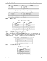
On-board Connector/Header Overview Intel® Server Board S1200V3RP 8.3.5 Pin Signal Name 6 FM_LCP_LEFT_N 7 FM_LCP_RIGHT_N HSBP_ I2C Header Table 34. HSBP_ I2C Header Pin-out (J2K4) Pin 1 2 3 Signal Name SMB_HSBP_3V3STBY_DATA GND SMB_HSBP_3V3STBY_CLK 8.3.6 HDD LED Header The server board includes a 2-pin hard drive activity LED header used with some SAS/SATA controller add-in cards. The header has the following pin-out. Table 35. HDD LED Header Pin-out (J1G2) Pin Signal Name 1 LED_HDD_ACT_N Pin 2 N/A Signal Name 8.3.7 Chassis Intrusion Header The server board includes a 2-pin chassis intrusion header which can be used when the chassis is configured with a chassis intrusion switch. The header has the following pin-out. Table 36. Chassis Intrusion Header Pin-out (J1F1) Header State Pins 1 and 2 closed Pins 1 and 2 open Description FM_INTRUDER_HDR_N is pulled HIGH. Chassis cover is closed. FM_INTRUDER_HDR_N is pulled LOW. Chassis cover is removed. 8.3.8 SATA SGPIO Header SGPIO uses a 5pin header, this is to incorporate a ground conductor as an SI improvement over previous generation products and based on measurement data indicating add the ground is strongly recommended. The 5pin connector will be consistent with other HSBPs, in this way cable commonality is improved. Table 37. SATA SGPIO Header Pin-out (J2K2) 8.3.9 Pin 1 2 3 4 5 IPMB Connector Signal Name SCLK SLOAD GND SDATAOUT0 SDATAOUT1 Table 38. IPMB Connector Pin-out (J2K1) 78 Revision 1.0
-
 1
1 -
2
-
3
-
4
-
5
-
6
-
7
-
8
-
9
-
10
-
11
-
12
-
13
-
14
-
15
-
16
-
17
-
18
-
19
-
20
-
21
-
22
-
23
-
24
-
25
-
26
-
27
-
28
-
29
-
30
-
31
-
32
-
33
-
34
-
35
-
36
-
37
-
38
-
39
-
40
-
41
-
42
-
43
-
44
-
45
-
46
-
47
-
48
-
49
-
50
-
51
-
52
-
53
-
54
-
55
-
56
-
57
-
58
-
59
-
60
-
61
-
62
-
63
-
64
-
65
-
66
-
67
-
68
-
69
-
70
-
71
-
72
-
73
-
74
-
75
-
76
-
77
-
78
-
79
-
80
-
81
-
82
-
83
-
84
-
 85
85 -
 86
86 -
 87
87 -
 88
88 -
 89
89 -
 90
90 -
 91
91 -
 92
92 -
 93
93 -
 94
94 -
 95
95 -
96
-
97
-
98
-
99
-
100
-
101
-
102
-
103
-
104
-
105
-
106
-
107
-
108
-
109
-
110
-
111
-
112
-
113
-
114
-
115
-
116
-
117
-
118
-
119
-
120
-
121
-
122
-
123
-
124
-
125
-
126
-
127
-
128
-
129
-
130
-
131
-
132
-
133
-
134
-
135
-
136
-
137
-
138
-
139
-
140
-
141
-
142
-
143
-
144
-
145
-
146
-
147
-
148
-
149
-
150
-
151
-
152
-
153
-
154
-
155
-
156
-
157
-
158
-
159
-
160
-
161
-
162
-
163
-
164
-
165
-
166
-
167
-
168
-
169
-
170
-
171
-
172
-
173
-
174
-
175
-
176
-
177
-
178
-
179
-
180
-
181
-
182
-
183
-
184
-
185
-
186
-
187
-
188
-
189
-
190
-
191
-
192
-
193
-
194
-
195
-
196
-
197
-
198
-
199
-
200
-
201
-
202
-
203
-
204
-
205
-
206
-
207
-
208
-
209
-
210
-
211
-
212
-
213
-
214
-
215
-
216
-
217
-
218
-
219
-
220
-
221
-
222
-
223
-
224
-
225
-
226
-
227
-
228
-
229
-
230
-
231
-
232
-
233
-
234
-
235
-
236
-
237
-
238
-
239
-
240
-
241
-
242
-
243
-
244
-
245
-
246
-
247
-
248
-
249
-
250
-
251
-
252
-
253
-
254
-
255
-
256
-
257
-
258
-
259
-
260
-
261
-
262
 |
 |
