Intel S1200RP Technical Product Specification - Page 88
System Management Headers
 |
View all Intel S1200RP manuals
Add to My Manuals
Save this manual to your list of manuals |
Page 88 highlights
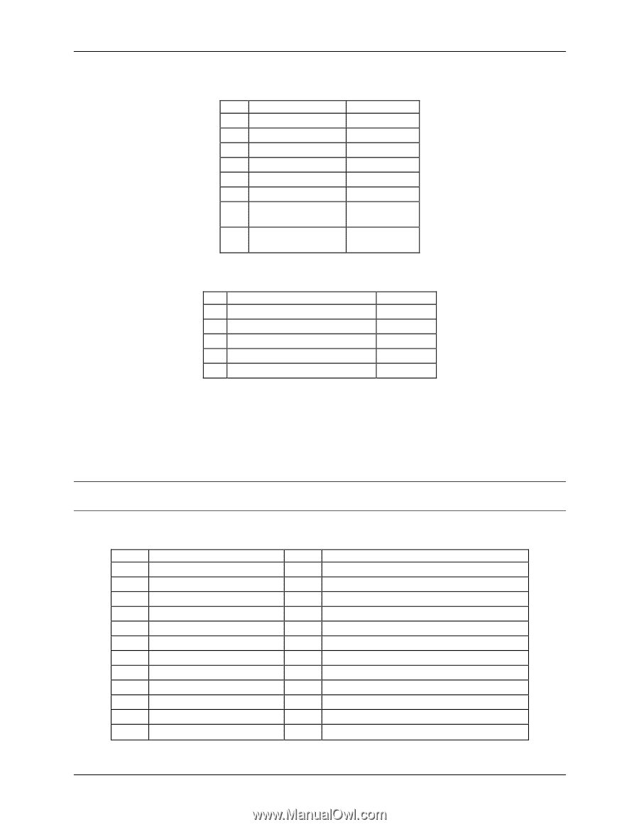
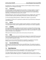
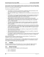
On-board Connector/Header Overview Intel® Server Board S1200V3RP Table 27. CPU Power Connector Pin-out (J9B1) Pin Signal 1 GND of Pin 5 2 GND of Pin 6 3 GND of Pin 7 4 GND of Pin 8 5 +12 Vdc CPU1 6 +12 Vdc CPU1 7 +12 Vdc DDR3_CPU1 8 +12 Vdc DDR3_CPU1 Color Black Black Black Black Yellow/black Yellow/black Yellow/black Yellow/black Table 28. Power Supply Auxiliary Signal Connector Pin-out (J9C3) Pin Signal 1 SMB_CLK_FP_PWR_R 2 SMB_DAT_FP_PWR_R 3 SMB_ALRT_3_ESB_R 4 3.3 V SENSE- 5 3.3 V SENSE+ Color Orange Black Red Yellow Green 8.3 System Management Headers 8.3.1 Intel® Remote Management Module 4 Dedicated NIC Connector A 30-pin Intel® RMM4 connector (J4C1) and a 7-pin Intel® RMM4 Lite connector (J4B1) are included on the server board to support the optional Intel® Remote Management Module 4 dedicated NIC module. This server board does not support third-party management cards. Note: This connector is not compatible with the previous generation Intel® Remote Management Modules (Intel® RMM/RMM2/RMM3) Table 29. Intel® RMM4 Dedicated NIC Module Connector Pin-out (J4C1) Pin Signal Name 1 3V3_AUX 3 3V3_AUX 5 GND 7 GND 9 GND 11 GND 13 GND 15 GND 17 GND 19 GND 21 GND 23 GND Pin 2 MDIO 4 MDC 6 TXD_0 8 TXD_1 10 TXD_2 12 TXD_3 14 TX_CTL 16 RX_CTL 18 RXD_0 20 RXD_1 22 RXD_2 24 RXD_3 Signal Name 76 Revision 1.0
-
 1
1 -
2
-
3
-
4
-
5
-
6
-
7
-
8
-
9
-
10
-
11
-
12
-
13
-
14
-
15
-
16
-
17
-
18
-
19
-
20
-
21
-
22
-
23
-
24
-
25
-
26
-
27
-
28
-
29
-
30
-
31
-
32
-
33
-
34
-
35
-
36
-
37
-
38
-
39
-
40
-
41
-
42
-
43
-
44
-
45
-
46
-
47
-
48
-
49
-
50
-
51
-
52
-
53
-
54
-
55
-
56
-
57
-
58
-
59
-
60
-
61
-
62
-
63
-
64
-
65
-
66
-
67
-
68
-
69
-
70
-
71
-
72
-
73
-
74
-
75
-
76
-
77
-
78
-
79
-
80
-
81
-
82
-
 83
83 -
 84
84 -
 85
85 -
 86
86 -
 87
87 -
 88
88 -
 89
89 -
 90
90 -
 91
91 -
 92
92 -
 93
93 -
94
-
95
-
96
-
97
-
98
-
99
-
100
-
101
-
102
-
103
-
104
-
105
-
106
-
107
-
108
-
109
-
110
-
111
-
112
-
113
-
114
-
115
-
116
-
117
-
118
-
119
-
120
-
121
-
122
-
123
-
124
-
125
-
126
-
127
-
128
-
129
-
130
-
131
-
132
-
133
-
134
-
135
-
136
-
137
-
138
-
139
-
140
-
141
-
142
-
143
-
144
-
145
-
146
-
147
-
148
-
149
-
150
-
151
-
152
-
153
-
154
-
155
-
156
-
157
-
158
-
159
-
160
-
161
-
162
-
163
-
164
-
165
-
166
-
167
-
168
-
169
-
170
-
171
-
172
-
173
-
174
-
175
-
176
-
177
-
178
-
179
-
180
-
181
-
182
-
183
-
184
-
185
-
186
-
187
-
188
-
189
-
190
-
191
-
192
-
193
-
194
-
195
-
196
-
197
-
198
-
199
-
200
-
201
-
202
-
203
-
204
-
205
-
206
-
207
-
208
-
209
-
210
-
211
-
212
-
213
-
214
-
215
-
216
-
217
-
218
-
219
-
220
-
221
-
222
-
223
-
224
-
225
-
226
-
227
-
228
-
229
-
230
-
231
-
232
-
233
-
234
-
235
-
236
-
237
-
238
-
239
-
240
-
241
-
242
-
243
-
244
-
245
-
246
-
247
-
248
-
249
-
250
-
251
-
252
-
253
-
254
-
255
-
256
-
257
-
258
-
259
-
260
-
261
-
262
 |
 |