JVC DLA-RS45U Command Communication Specification for D-ILA Projectors (v1.7 f - Page 31
Panel Alignment zone Data [Panel AlignmentZone Red, Blue]
 |
View all JVC DLA-RS45U manuals
Add to My Manuals
Save this manual to your list of manuals |
Page 31 highlights
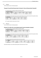
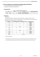
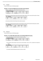
4 Command control 4.10 Panel Alignment (zone) Data [Panel Alignment(Zone) Red, Blue] Used for transmitting operation and referencing Panel Alignment (zone) data Corresponding for X70/XC788/RS55, X90/XC988/RS65 only Command Code HEX 0x50 0x52 0x50 0x42 Table 4-18 PANELALIGNMENT(ZONE) DATA CMD ASCII 'P' 'R' 'P' 'B' Function Data of Red [Panel Alignment(Zone)Red] Data of Blue [Panel Alignment(Zone)Blue transmitting referencing Parameters Data Length: 256 Horizontal and Vertical data of 11x11 Adjustment zone composed of binary data. Data could be -31 (0xE1) to +31(0x1F). Data is assigned by 2 bytes and its order is from Horizontal to Vertical. The order of Adjustment zone is shown at a table below. 121 (Adjustment zone) x 2 (Horizontal / Vertical) + 13 (reserved) =256 Byte Data No. 1 2 3 4 5 6 21 22 23 24 239 240 241 242 243-256 Horizontal position of zone Vertical position of zone 0 0 1 0 2 0 (skip) 10 0 0 1 (skip) 9 10 10 10 Reserved Horizontal / Vertical Horizontal Vertical Horizontal Vertical Horizontal Vertical Horizontal Vertical Horizontal Vertical Horizontal Vertical Horizontal Vertical The Byte order is little endian. When the projector is not powered on and it receives the command, the projector ignores the command and does not respond. If the projector receives gamma data larger than 256 bytes, it is judged as invalid data and the projector does not respond. 31 / 80 PJ03220107B
-
 1
1 -
2
-
3
-
4
-
5
-
6
-
7
-
8
-
9
-
10
-
11
-
12
-
13
-
14
-
15
-
16
-
17
-
18
-
19
-
20
-
21
-
22
-
23
-
24
-
25
-
 26
26 -
 27
27 -
 28
28 -
 29
29 -
 30
30 -
 31
31 -
 32
32 -
 33
33 -
 34
34 -
 35
35 -
 36
36 -
37
-
38
-
39
-
40
-
41
-
42
-
43
-
44
-
45
-
46
-
47
-
48
-
49
-
50
-
51
-
52
-
53
-
54
-
55
-
56
-
57
-
58
-
59
-
60
-
61
-
62
-
63
-
64
-
65
-
66
-
67
-
68
-
69
-
70
-
71
-
72
-
73
-
74
-
75
-
76
-
77
-
78
-
79
-
80
 |
 |