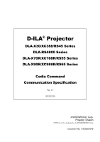
JVC DLA-RS45U Command Communication Specification for D-ILA Projectors (v1.7 f - Page 4

Table Number

Page 4 highlights

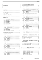
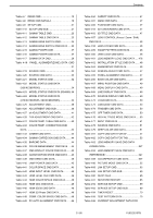
Contents CONTENTS 1 OUTLINE 7 2 INTERFACE 7 2.1 Terminal 7 2.2 External Controller Connector 7 2.3 Communication Line 7 3 PROTOCOL 8 3.1 Communication specification 8 3.2 Data format 8 3.3 Header table 8 3.4 Unit ID table 9 3.5 Command table 9 3.6 Parameter 10 3.6.1 Numeric value parameters 10 3.6.2 Special parameter 10 3.7 Exit code 11 3.8 Error handling 11 3.9 Communication sequence 12 4 COMMAND CONTROL 13 4.1 NULL command 13 4.1.1 Operation 13 4.1.2 Reference 13 4.2 Power [PoWer 14 4.2.1 Operation 14 4.2.2 Reference 15 4.3 Input [InPut 16 4.3.1 Operation 17 4.3.2 Reference 18 4.4 Remote control pass-through [RemoteCode]19 4.4.1 Operation 20 4.5 Setup [SetUp 21 4.5.1 Operation 22 4.6 Gamma table [GammaTable 23 4.6.1 Operation 24 4.6.2 Reference 24 4.7 Gamma Bank switch [Gamma-bankSwitch].. 25 4.7.1 Operation 26 4.7.2 Reference 26 4.8 Gamma coefficient of Gamma table "Custom1/2/3" [GammaPower 27 4.8.1 Operation 28 4.8.2 Reference 28 4.9 Gamma data of Gamma table "Custom 1/2/3" [GammaRed, Green, Blue 29 4.9.1 Operation 30 4.9.2 Reference 30 4.10 Pannel Alignment (zone) data [Panel Alignment(Zone) Red, Blue 31 4.10.1 Operation 32 4.10.2 Reference 32 4.11 Source Asking [SourCe 33 4.11.1 Reference 33 4.12 Model status asking [MoDel 34 4.12.1 Reference 35 4.13 Picture adjustment [Adjustment of Picture] 36 4.13.1 Operation 57 4.13.2 Reference 61 4.14 LAN setup [Lan Setup 65 4.14.1 Operation 66 4.14.2 Reference 67 4.15 Service setup [Service Setup 69 4.15.1 Operation 74 4.15.2 Reference 77 5 ADDITIONAL INFORMATION FOR ISF ADJUSTMENT 79 5.1 State Transitoin Diagram 79 5.2 Remote Controll Code 79 6 ADDITIONAL INFORMATION FOR THX ADJUSTMENT 80 5.1 State Transitoin Diagram 80 5.2 Remote Controll Code 80 Table Number Table 4-1 NULL CMD 13 Table 4-2 POWER CMD 14 Table 4-3 POWER CMD DATA0 14 Table 4-4 POWER CMD STATUS 15 Table 4-5 INPUT CMD 16 Table 4-6 INPUT CMD DATA 16 4 / 80 PJ03220107B

  • 1
  • 2
  • 3
  • 4
  • 5
  • 6
  • 7
  • 8
  • 9
  • 10
  • 11
  • 12
  • 13
  • 14
  • 15
  • 16
  • 17
  • 18
  • 19
  • 20
  • 21
  • 22
  • 23
  • 24
  • 25
  • 26
  • 27
  • 28
  • 29
  • 30
  • 31
  • 32
  • 33
  • 34
  • 35
  • 36
  • 37
  • 38
  • 39
  • 40
  • 41
  • 42
  • 43
  • 44
  • 45
  • 46
  • 47
  • 48
  • 49
  • 50
  • 51
  • 52
  • 53
  • 54
  • 55
  • 56
  • 57
  • 58
  • 59
  • 60
  • 61
  • 62
  • 63
  • 64
  • 65
  • 66
  • 67
  • 68
  • 69
  • 70
  • 71
  • 72
  • 73
  • 74
  • 75
  • 76
  • 77
  • 78
  • 79
  • 80

Contents
4 / 80
PJ03220107B
CONTENTS
1 OUTLINE
....................................................
7
2 INTERFACE
...............................................
7
2.1
Terminal
...........................................................
7
2.2
External Controller Connector
.........................
7
2.3
Communication Line
.......................................
7
3 PROTOCOL
...............................................
8
3.1
Communication specification
..........................
8
3.2
Data format
......................................................
8
3.3
Header table
....................................................
8
3.4
Unit ID table
.....................................................
9
3.5
Command table
...............................................
9
3.6
Parameter
.....................................................
10
3.6.1
Numeric value parameters
.............................
10
3.6.2
Special parameter
..........................................
10
3.7
Exit code
.......................................................
11
3.8
Error handling
................................................
11
3.9
Communication sequence
.............................
12
4 COMMAND CONTROL
............................
13
4.1
NULL command
............................................
13
4.1.1
Operation
.......................................................
13
4.1.2
Reference
......................................................
13
4.2
Power [PoWer]
..............................................
14
4.2.1
Operation
.......................................................
14
4.2.2
Reference
......................................................
15
4.3
Input [InPut]
...................................................
16
4.3.1
Operation
.......................................................
17
4.3.2
Reference
......................................................
18
4.4
Remote control pass-through [RemoteCode]19
4.4.1
Operation
.......................................................
20
4.5
Setup [SetUp]
................................................
21
4.5.1
Operation
.......................................................
22
4.6
Gamma table [GammaTable]
........................
23
4.6.1
Operation
.......................................................
24
4.6.2
Reference
......................................................
24
4.7
Gamma Bank switch [Gamma-bankSwitch]..25
4.7.1
Operation
.......................................................
26
4.7.2
Reference
......................................................
26
4.8
Gamma coefficient of Gamma
table ”Custom1/2/3” [GammaPower]
......................
27
4.8.1
Operation
......................................................
28
4.8.2
Reference
......................................................
28
4.9
Gamma data of Gamma table “Custom 1/2/3”
[GammaRed, Green, Blue]
.....................................
29
4.9.1
Operation
......................................................
30
4.9.2
Reference
......................................................
30
4.10
Pannel Alignment (zone) data [Panel
Alignment(Zone) Red, Blue] ………………………. 31
4.10.1
Operation …...………………………………… 32
4.10.2
Reference
......................................................
32
4.11
Source Asking [SourCe]
.. ..........................
33
4.11.1
Reference
......................................................
33
4.12
Model status asking [MoDel]
.....................
34
4.12.1
Reference
......................................................
35
4.13
Picture adjustment [Adjustment of Picture] 36
4.13.1
Operation
......................................................
57
4.13.2
Reference
......................................................
61
4.14
LAN setup [Lan Setup]
..............................
65
4.14.1
Operation
......................................................
66
4.14.2
Reference
......................................................
67
4.15
Service setup [Service Setup]
...................
69
4.15.1
Operation
......................................................
74
4.15.2
Reference
......................................................
77
5 ADDITIONAL INFORMATION FOR ISF
ADJUSTMENT …………………………….. 79
5.1
State Transitoin Diagram ……………………. 79
5.2
Remote Controll Code
……………………. 79
6 ADDITIONAL INFORMATION FOR THX
ADJUSTMENT …………………………….. 80
5.1
State Transitoin Diagram ……………………. 80
5.2
Remote Controll Code
……………………. 80
Table Number
Table 4-1
NULL CMD
................................................
13
Table 4-2
POWER CMD
...........................................
14
Table 4-3
POWER CMD DATA0
...............................
14
Table 4-4
POWER CMD STATUS
............................
15
Table 4-5
INPUT CMD
..............................................
16
Table 4-6
INPUT CMD DATA
...................................
16