JVC GR-DV3000U Instructions - Page 82

Controls, Connectors, Indicators, Other Parts

Page 82 highlights

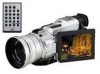
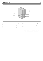
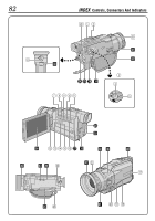
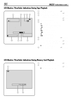
Controls 1 Snapshot Button [SNAPSHOT pg. 20, 21, 61 2 • Power Zoom Lever [T/W pg. 22 • Speaker/Headphone Volume Control [VOLUME pg. 25 3 Power Switch [ , , , OFF pg. 14 4 Recording Start/Stop Button pg. 18 5 Lock Button pg. 14 6 Diopter Adjustment Control pg. 10 7 • Stop Button [5 pg. 25 • Program AE Button [PROG.AE pg. 38 8 • Rewind Button [2 pg. 25 • NIGHT Button pg. 38 9 • Play/Pause Button [4/6 pg. 25 • BACKLIGHT Button pg. 40 0 • Fast-Forward Button [3 pg. 25 • FADE/WIPE Button pg. 36 ! VIDEO/MEMORY Switch [VIDEO, MEMORY pg. 14 @ TITLE Button pg. 48 # INDEX Button pg. 27, 45, 48 $ • NAVI Button pg. 42 • SELECT Button pg. 26, 49 - 53 % • E-MAIL Button pg. 46 • INFO Button pg. 27 ^ D. SOUND Button pg. 45 & Monitor Open Button [PUSH OPEN] ..... ੬ pg. 18 * FOCUS Button pg. 24 ( EXPOSURE Button pg. 40 ) • MENU Wheel [v, w, PUSH pg. 28 • LCD Monitor Brightness Control pg. 18 q Manual Focus Ring pg. 24 w Battery Release Switch [BATT. RELEASE pg. 9 e OPEN/EJECT Switch pg. 12 Connectors The connectors r to y are located beneath a cover. r Headphone Connector [PHONE pg. 72 No sound is output from the speaker when headphones are connected to this connector. EN 83 t PRINTER Connector Connect to the optional printer equipped with a PRINT DATA connector. Refer to the separate "FOR OWNERS OF AN OPTIONAL PRINTER" instruction sheet. y Audio/Video Input/Output Connector [AV pg. 54, 59, 67 To connect a cable to the connector u, open the LCD monitor. u Digital Video Connector [DV IN/OUT] (i.Link pg. 56, 58, 60 * i.Link refers to the IEEE1394-1995 industry specification and extensions thereof. The logo is used for products compliant with the i.Link standard. i Multi Connector When attaching the Jack Box to the camcorder, this part is connected. Indicators o Power Lamp pg. 18 p Tally Lamp pg. 18 Other Parts Q Speaker pg. 42 W Grip Strap pg. 10 E Shoulder Strap Eyelets pg. 10 R Viewfinder Cleaning Hatch pg. 80 T Battery Pack Mount pg. 9 Y LCD Monitor pg. 18, 19 U Lens Hood pg. 6 I Info-Shoe Attach the optional video light/flash/zoom microphone. O Camera Sensor Be careful not to cover this area, a sensor necessary for shooting is built-in here. P Viewfinder pg. 10 a Remote Sensor pg. 62 s Stereo Microphone pg. 72 d Stud Hole pg. 10 f Tripod Mounting Socket pg. 10 g MEMORY CARD Cover pg. 13

  • 1
  • 2
  • 3
  • 4
  • 5
  • 6
  • 7
  • 8
  • 9
  • 10
  • 11
  • 12
  • 13
  • 14
  • 15
  • 16
  • 17
  • 18
  • 19
  • 20
  • 21
  • 22
  • 23
  • 24
  • 25
  • 26
  • 27
  • 28
  • 29
  • 30
  • 31
  • 32
  • 33
  • 34
  • 35
  • 36
  • 37
  • 38
  • 39
  • 40
  • 41
  • 42
  • 43
  • 44
  • 45
  • 46
  • 47
  • 48
  • 49
  • 50
  • 51
  • 52
  • 53
  • 54
  • 55
  • 56
  • 57
  • 58
  • 59
  • 60
  • 61
  • 62
  • 63
  • 64
  • 65
  • 66
  • 67
  • 68
  • 69
  • 70
  • 71
  • 72
  • 73
  • 74
  • 75
  • 76
  • 77
  • 78
  • 79
  • 80
  • 81
  • 82
  • 83
  • 84
  • 85
  • 86
  • 87
  • 88
  • 89
  • 90
  • 91
  • 92
  • 93
  • 94
  • 95
  • 96

EN
83
Controls
1
Snapshot Button
[SNAPSHOT]
.............................
±
pg. 20, 21, 61
2
• Power Zoom Lever [T/W]
.....................
±
pg. 22
• Speaker/Headphone Volume Control
[VOLUME]
...........................................
±
pg. 25
3
Power Switch [
,
,
, OFF]
.......
±
pg. 14
4
Recording Start/Stop Button
..................
±
pg. 18
5
Lock Button
............................................
±
pg. 14
6
Diopter Adjustment Control
...................
±
pg. 10
7
• Stop Button [
5
]
....................................
±
pg. 25
• Program AE Button [PROG.AE]
..........
±
pg. 38
8
• Rewind Button [
2
]
.............................
±
pg. 25
• NIGHT Button
......................................
±
pg. 38
9
• Play/Pause Button [
4
/
6
]
.....................
±
pg. 25
• BACKLIGHT Button
.............................
±
pg. 40
0
• Fast-Forward Button [
3
]
....................
±
pg. 25
• FADE/WIPE Button
..............................
±
pg. 36
!
VIDEO/MEMORY Switch
[VIDEO, MEMORY]
................................
±
pg. 14
@
TITLE Button
.........................................
±
pg. 48
#
INDEX Button
............................
±
pg. 27, 45, 48
$
• NAVI Button
.........................................
±
pg. 42
• SELECT Button
.....................
±
pg. 26, 49 – 53
%
• E-MAIL Button
.....................................
±
pg. 46
• INFO Button
.........................................
±
pg. 27
^
D. SOUND Button
..................................
±
pg. 45
&
Monitor Open Button [PUSH OPEN]
.....
±
pg. 18
*
FOCUS Button
.......................................
±
pg. 24
(
EXPOSURE Button
...............................
±
pg. 40
)
• MENU Wheel [
,
, PUSH]
................
±
pg. 28
• LCD Monitor Brightness Control
..........
±
pg. 18
q
Manual Focus Ring
................................
±
pg. 24
w
Battery Release Switch
[BATT. RELEASE]
....................................
±
pg. 9
e
OPEN/EJECT Switch
............................
±
pg. 12
Connectors
The connectors
r
to
y
are located beneath a cover.
r
Headphone Connector [PHONE]
...........
±
pg. 72
No sound is output from the speaker when
headphones are connected to this connector.
t
PRINTER Connector
Connect to the optional printer equipped with a
PRINT DATA connector. Refer to the separate
“FOR OWNERS OF AN OPTIONAL PRINTER”
instruction sheet.
y
Audio/Video Input/Output Connector
[AV]
............................................
±
pg. 54, 59, 67
To connect a cable to the connector
u
, open the LCD
monitor.
u
Digital Video Connector
[DV IN/OUT] (i.Link*)
.................
±
pg. 56, 58, 60
* i.Link refers to the IEEE1394-1995 industry
specification and extensions thereof. The
logo
is used for products compliant with the i.Link
standard.
i
Multi Connector
When attaching the Jack Box to the camcorder,
this part is connected.
Indicators
o
Power Lamp
...........................................
±
pg. 18
p
Tally Lamp
.............................................
±
pg. 18
Other Parts
Q
Speaker
.................................................
±
pg. 42
W
Grip Strap
..............................................
±
pg. 10
E
Shoulder Strap Eyelets
..........................
±
pg. 10
R
Viewfinder Cleaning Hatch
....................
±
pg. 80
T
Battery Pack Mount
.................................
±
pg. 9
Y
LCD Monitor
....................................
±
pg. 18, 19
U
Lens Hood
...............................................
±
pg. 6
I
Info-Shoe
Attach the optional video light/flash/zoom
microphone.
O
Camera Sensor
Be careful not to cover this area, a sensor
necessary for shooting is built-in here.
P
Viewfinder
..............................................
±
pg. 10
a
Remote Sensor
......................................
±
pg. 62
s
Stereo Microphone
................................
±
pg. 72
d
Stud Hole
...............................................
±
pg. 10
f
Tripod Mounting Socket
.........................
±
pg. 10
g
MEMORY CARD Cover
.........................
±
pg. 13