Konica Minolta C83hc High Chroma GBC PUNCH G2 User Manual - Page 10
Die Set User Manual
 |
View all Konica Minolta C83hc High Chroma manuals
Add to My Manuals
Save this manual to your list of manuals |
Page 10 highlights
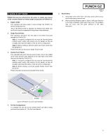
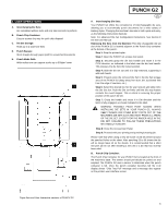
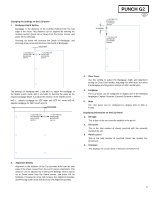
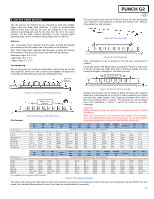
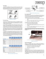
8. DIE SET USER MANUAL The die sets for the PUNCH G2 are intended to work with multiple paper sizes and sheet feed directions. In order to accommodate different sheet sizes this die set must be configured to the correct number of punching pins and the die stop must be set to the proper position. The die label contains information on the common paper punching sizes, for the uncommon sizes please refer to Table 8.1. Glossary LEF- Long Edge Feed- Indicates that the paper is being fed through the machine so that the longer side of the sheet will be punched. SEF- Short Edge Feed- Indicates that the paper is being fed through the machine so that the shorter side of the sheet will be punched. Statement Paper- 8.5" X 5.5" Legal Paper- 8.5" X 14" Ledger Paper- 11" X 17" Pin Numbering Die punching pins are numbered sequentially starting from the handle end. Figure 8.1 shows a 47 hole coil die as an example. All square and round hole die sets follow the same pin numbering format. Pin #1 PUNCH G2 EN To remove punch pins from the PUNCH G2 first turn the two Quarter Turn Fasteners CCW direction to release the pressure bar. Remove the pressure bar and set aside. Figure 8.3 Pressure Bar Figure 8.4 Pin Removal Note: Lubricating oil may be present on the die pins, wear gloves if needed. Lift up and remove the desired pins according to Table 8.1. Store pins in the pin storage tray inside front door of machine making sure pins cannot be dropped, damaged or lost while removed. Dowel Pin Holes Pin #47 Figure 8.1 Coil Die Set Pin Numbering Quarter Turn Fastener Pin Removal Figure 8.2 Pressure Bar Removal Figure 8.5 Replace Pressure Bar Replace the pressure bar by lining up dowel pin holes with exposed dowel pins. Hold pressure bar so that it is seats completely over dowel pins and then rotate Quarter Turn Fasteners clockwise until a click is felt to lock pressure bar in position. The pressure bar can be locked only if the orientation is correct, it cannot be locked in any other orientation. Important! Before reinserting, clean the punch pin to remove any dust or foreign substances. Make sure pressure bar is attached and both Quarter Turn Fasteners are in the locked position prior to inserting the die set into the machine or serious damage can occur to both the machine and die set. Coil Rnd US Paper Sizes Konica Minolta Part Number LTR LEF 2, 47 LTR SEF 7, 42 STATEMENT LEF 7, 42 LEGAL SEF 7, 42 LEDGER SEF 2, 47 9" x 12" LEF 1, 2, 47 9" x 12" SEF 6, 7, 42, 43 12" x 18" SEF 1, 2, 47 Wire 2:1 Rnd 1, 23 NONE NONE NONE 1, 23 1, 23 3, 21 1, 23 Wire 3:1 Rnd 1, 34 5, 31 5, 31 5, 31 1, 34 1, 34 5, 31 1, 34 3 Hole 8mm 3/5/7 2/4 2/4 2/4 VeloBind Hole Hole Hole Hole 11 Hole 8mm 8mm 6.5mm SCAN LTR Pin Numbers to Remove Based On Paper Size or Orientation VeloBind 12 Hole A4 CombBind Wire 2:1 Sq NONE 3H/5H/7H N/A N/A N/A NONE N/A 1, 21 1, 23 N/A N/A N/A N/A N/A N/A N/A NONE NONE N/A N/A N/A N/A N/A N/A N/A NONE NONE N/A N/A N/A N/A N/A N/A N/A NONE NONE NONE 3H/5H/7H N/A N/A N/A NONE N/A 1, 21 1, 23 NONE 3H/5H/7H N/A N/A N/A NONE N/A 1, 21 1, 23 N/A N/A N/A N/A N/A N/A N/A 3, 19 3, 21 NONE 3H/5H/7H N/A N/A N/A NONE N/A 1, 21 1, 23 Wire 3:1 Sq 1,34 5,31 5,31 5,31 1, 34 1, 34 5, 31 1, 34 Coil Rnd ISO Paper Sizes Konica Minolta Part Number A4 LEF NONE A4 SEF 7, 41 A5 LEF 7, 41 A3 SEF NONE SRA4 LEF NONE SRA4 SEF 6, 7, 42, 41 SRA3 SEF NONE Wire 2:1 Rnd NONE 4, 21 4, 21 NONE NONE 4, 21 NONE *For CombBind 20H Configuration Pull Pin Number 1 Wire 3:1 Rnd NONE 5, 30 5, 30 NONE NONE 4, 5, 30, 31 NONE 3 Hole 8mm 3/5/7 2/4 2/4 2/4 VeloBind Hole Hole Hole Hole 11 Hole 8mm 8mm 6.5mm SCAN LTR Pin Numbers to Remove Based On Paper Size or Orientation VeloBind 12 Hole A4 CombBind Wire 2:1 Sq N/A N/A 2H/4H 2H/4H NONE N/A NONE NONE NONE N/A N/A 2H 2H NONE N/A N/A 4, 19 4, 21 N/A N/A 2H 2H NONE N/A N/A 4,19 4, 21 N/A N/A 2H/4H 2H/4H NONE N/A NONE NONE NONE N/A N/A 2H/4H 2H/4H NONE N/A NONE NONE NONE N/A N/A N/A N/A NONE N/A N/A 4, 19 4, 21 N/A N/A 2H/4H 2H/4H NONE N/A NONE NONE NONE Table 8.1 Pin Removal Guide Wire 3:1 Sq NONE 5, 30 5, 30 NONE NONE 4, 5, 30, 31 NONE The above chart shows the information on which pins need to be removed to correctly punch each sheet size and configuration that the PUNCH G2 can accept. For standard offering dies not found in the chart no pin adjustment is necessary. 10
-
 1
1 -
2
-
3
-
4
-
 5
5 -
 6
6 -
 7
7 -
 8
8 -
 9
9 -
 10
10 -
 11
11 -
 12
12 -
 13
13 -
 14
14 -
 15
15 -
16
-
17
-
18
-
19
-
20
-
21
-
22
-
23
-
24
-
25
-
26
-
27
-
28
-
29
-
30
-
31
-
32
-
33
-
34
-
35
-
36
-
37
-
38
-
39
-
40
-
41
-
42
-
43
-
44
-
45
-
46
-
47
-
48
-
49
-
50
-
51
-
52
-
53
-
54
-
55
-
56
-
57
-
58
-
59
-
60
-
61
-
62
-
63
-
64
-
65
-
66
-
67
-
68
-
69
-
70
-
71
-
72
-
73
-
74
-
75
-
76
-
77
-
78
-
79
-
80
-
81
-
82
-
83
-
84
-
85
-
86
-
87
-
88
-
89
-
90
-
91
-
92
 |
 |
