Konica Minolta C83hc High Chroma GBC PUNCH G2 User Manual - Page 11
Pin Addition, Table 8.2 Die Stop Position Guide, Coil Die Stop Position,
 |
View all Konica Minolta C83hc High Chroma manuals
Add to My Manuals
Save this manual to your list of manuals |
Page 11 highlights
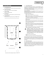
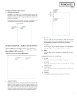
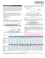
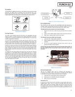
Pin Addition The process for adding punch pins is the same as pin removal except that pins are added and not removed once the pressure bar is off. When replacing punch pins make certain that the pins are completely seated against the pin retainer prior to reattaching the pressure bar. CORRECT INCORRECT CORRECT INCORRECT Figure 8.6 Pin Addition Die Stop Position On some of the PUNCH G2 die sets there is an adjustable die stop which is used to re-center the die set for certain sheet sizes, as shown in Figure 8.7. For die sets without a die stop knob there is no die stop position adjustment necessary. For units with a die stop knob, the die stop must be set to the correct position or the punched holes will not be centered on the sheet. The common paper sizes are shown on the die stop handle label below the die stop knob, for the uncommon paper sizes please refer to Table 8.2. Position A is when the arrow on the die stop knob points down towards the handle and lines up with the lower arrow on the die stop handle label. Position B is when the arrow on the die stop knob points to the side and lines up with the side arrow on the die stop handle label. (See Figure 8.7) To change the die stop position first remove the die from the machine and place on a flat stable surface. While holding the die in a stable position push down on the die stop knob until the knob is free to rotate. Then turn the knob until the arrow on the knob lines up with the desired arrow on the die stop handle label. Once the arrows line up, release the die stop knob making sure that the metal die stop on the bottom fully seats against the die plate. US Paper Sizes Konica Minolta Part Number LTR LEF LTR SEF STATEMENT LEF LEGAL SEF LEDGER SEF 9" x 12" LEF 9" x 12" SEF 12" x 18" SEF Coil Rnd Wire 2:1 Rnd Wire 3:1 Rnd CombBind Wire 2:1 Sq Wire 3:1 Sq Die Stop Position Based On Paper Size or Orientation B A A A A A B A B A A B B A B A A B B A B A A B B A A A A A B A A A A A B A B A A B B A A A A A ISO Paper Sizes Konica Minolta Part Number A4 LEF A4 SEF A5 LEF A3 SEF SRA4 LEF SRA4 SEF SRA3 SEF Coil Rnd Wire 2:1 Rnd Wire 3:1 Rnd CombBind Wire 2:1 Sq Wire 3:1 Sq Die Stop Position Based On Paper Size or Orientation A A A A* A A A A A B B A A A A B B A A A A A* A A A A A A* A A A B A B B A A A A A* A A *For CombBind 20H Configuration set to die stop position B Table 8.2 Die Stop Position Guide PUNCH G2 EN Die Stop Knob Position B Die Stop Handle Label Position A Figure 8.7 Coil Die Stop Position Die Set Maintenance The PUNCH G2 die set must be periodically oiled and greased to maintain proper functionality and prevent premature failure of the die set. The die set should be oiled and inspected every 100K cycles. To lubricate die set pins that do not have felt pads: 1. Depress the die set so that the pins protrude from the bottom plate. 2. Apply a drop of high quality machine oil to the end of each pin. 3. Wipe clean, leaving a light coat of oil on them. To lubricate die set pins that have felt pads: 1. Lubricate with a high quality machine oil. 2. Apply oil lightly along the length of the pad [1], but do not over saturate. 3. Do not use spray lubricants because they tend to dry up quickly and leave a sticky residue. Oil from the die may blemish the first few punched sheets after oil has been applied. Run test punched copies until clean copies can be made. Figure 8.8 Lubrication Die Set Shoulder Bolts The die set shoulder bolts must be checked and lubricated as necessary every 200K cycles. If the grease is missing from the springs or shoulder bolts [2] then additional grease must be applied. 1. Lubricate with a high quality Teflon-based grease. 2. Apply grease to shoulder bolts and springs [2] 3. Wipe up any excess grease. End of Die Life If a die set is at the end of its life it will tend to cause paper jams due to hanging paper chips. This is a result of die plate wear and not pin wear, which cannot be corrected. When this occurs, the die set must be replaced with a new one. Attempting to replace or sharpen pins will not correct the issue since the wear is in the plates and therefore is not recommended. 11
-
 1
1 -
2
-
3
-
4
-
5
-
 6
6 -
 7
7 -
 8
8 -
 9
9 -
 10
10 -
 11
11 -
 12
12 -
 13
13 -
 14
14 -
 15
15 -
 16
16 -
17
-
18
-
19
-
20
-
21
-
22
-
23
-
24
-
25
-
26
-
27
-
28
-
29
-
30
-
31
-
32
-
33
-
34
-
35
-
36
-
37
-
38
-
39
-
40
-
41
-
42
-
43
-
44
-
45
-
46
-
47
-
48
-
49
-
50
-
51
-
52
-
53
-
54
-
55
-
56
-
57
-
58
-
59
-
60
-
61
-
62
-
63
-
64
-
65
-
66
-
67
-
68
-
69
-
70
-
71
-
72
-
73
-
74
-
75
-
76
-
77
-
78
-
79
-
80
-
81
-
82
-
83
-
84
-
85
-
86
-
87
-
88
-
89
-
90
-
91
-
92
 |
 |
