Konica Minolta PS5000C Operation Manual - Page 25
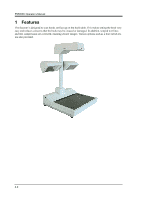
Part identification and functions
 |
View all Konica Minolta PS5000C manuals
Add to My Manuals
Save this manual to your list of manuals |
Page 25 highlights
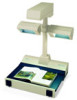
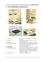
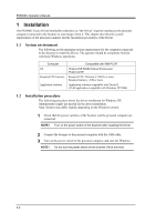
2 Part identification and functions 1 Chapter 2 Overview 2 6 14 7 8 5 3 9 11 12 13 10 4 1. Head unit: 2. Lamp unit: 3. Book table: 4. Book cradle unit (Option): 5. Power switch: 6. USB connector: 7. Option switch connector: 8. Power cord socket: The CCD sensor is housed in this unit. This sensor scans the original. Illuminates the original so the CCD sensor can read the original more proficiently. Place the original (book, sheet) face up on this table. Enable enhanced scanning of book originals by adjusting to the contours of the book. See pages 4-8 through 4-13 for detailed information and limitations. Turns the Scanner ON/OFF. Connect the USB cable that is supplied with the equipment. Connect the foot switch/the manual switch (option). Use the left terminal (viewed from the rear) to read the right page when the option switch is pressed, and the right terminal for the left page. Either terminal can be used when reading two spread pages. Plug the power cord into this socket. 2-3
-
 1
1 -
2
-
3
-
4
-
5
-
6
-
7
-
8
-
9
-
10
-
11
-
12
-
13
-
14
-
15
-
16
-
17
-
18
-
19
-
 20
20 -
 21
21 -
 22
22 -
 23
23 -
 24
24 -
 25
25 -
 26
26 -
 27
27 -
 28
28 -
 29
29 -
 30
30 -
31
-
32
-
33
-
34
-
35
-
36
-
37
-
38
-
39
-
40
-
41
-
42
-
43
-
44
-
45
-
46
-
47
-
48
-
49
-
50
-
51
-
52
-
53
-
54
-
55
-
56
-
57
-
58
-
59
-
60
-
61
-
62
-
63
-
64
-
65
-
66
-
67
-
68
-
69
-
70
-
71
-
72
-
73
-
74
-
75
-
76
 |
 |
