Lenovo E200 Hardware Maintenance Manual (HMM) - 3000 E200 (type 7848) - Page 104
Notes
 |
View all Lenovo E200 manuals
Add to My Manuals
Save this manual to your list of manuals |
Page 104 highlights
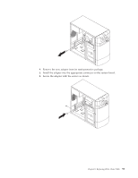
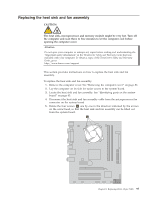
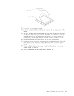
6. Lift the failing heat sink and fan assembly off the system board. Notes: a. You might have to gently twist the heat sink and fan assembly to free it from the microprocessor. b. Do not touch the thermal grease while handling the heat sink and fan assembly. 7. Position the new heat sink and fan assembly on the microprocessor so that the four screws are aligned with the holes on the system board. Note: Position the new heat sink and fan assembly so that the heat sink and fan assembly cable is toward the microprocessor fan connector on the system board. 8. Alternate rotating each screw in the opposite direction indicated by the arrows on the screw head, until the heat sink and fan assembly is secured to the system board. 9. Connect the heat sink and fan assembly cable to the microprocessor fan connector on the system board. 10. Go to "Completing the FRU replacement" on page 107. 98 Lenovo E200 Hardware Maintenance Manual
-
 1
1 -
2
-
3
-
4
-
5
-
6
-
7
-
8
-
9
-
10
-
11
-
12
-
13
-
14
-
15
-
16
-
17
-
18
-
19
-
20
-
21
-
22
-
23
-
24
-
25
-
26
-
27
-
28
-
29
-
30
-
31
-
32
-
33
-
34
-
35
-
36
-
37
-
38
-
39
-
40
-
41
-
42
-
43
-
44
-
45
-
46
-
47
-
48
-
49
-
50
-
51
-
52
-
53
-
54
-
55
-
56
-
57
-
58
-
59
-
60
-
61
-
62
-
63
-
64
-
65
-
66
-
67
-
68
-
69
-
70
-
71
-
72
-
73
-
74
-
75
-
76
-
77
-
78
-
79
-
80
-
81
-
82
-
83
-
84
-
85
-
86
-
87
-
88
-
89
-
90
-
91
-
92
-
93
-
94
-
95
-
96
-
97
-
98
-
 99
99 -
 100
100 -
 101
101 -
 102
102 -
 103
103 -
 104
104 -
 105
105 -
 106
106 -
 107
107 -
 108
108 -
 109
109 -
110
-
111
-
112
-
113
-
114
-
115
-
116
-
117
-
118
-
119
-
120
-
121
-
122
-
123
-
124
 |
 |