Lenovo E200 Hardware Maintenance Manual (HMM) - 3000 E200 (type 7848) - Page 113
Replacing, power, switch, assembly, Completing, replacement
 |
View all Lenovo E200 manuals
Add to My Manuals
Save this manual to your list of manuals |
Page 113 highlights
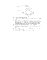
Replacing the power switch or LED assembly Attention Do not open your computer or attempt any repair before reading and understanding the "Important safety information" in the ThinkCentre Safety and Warranty Guide that came with your computer. To obtain a copy of the ThinkCentre Safety and Warranty Guide, go to: http://www.lenovo.com/support 1. Disconnect the power switch/LED assembly cable from the system board. See "Identifying parts on the system board" on page 85. 2. Remove the front bezel. See "Removing and replacing the front bezel" on page 88. 3. Remove the power switch/LED assembly by disconnecting it from the inside of the bezel. 4. Install the new power switch/LED assembly into the bezel. 5. Route the cable for the new power switch/LED assembly through the hole in the chassis and to the system board. 6. Reinstall the bezel. See "Removing and replacing the front bezel" on page 88. 7. Reconnect the power switch/LED cable to the system board. 8. Go to "Completing the FRU replacement." Completing the FRU replacement After replacing FRUs, you need to install any removed parts, replace the cover, and reconnect any cables, including telephone lines and power cords. Also, depending on the FRU that is replaced, you might need to confirm the updated information in the Setup Utility program. Note: When the power cord is first plugged in, the computer might appear to turn on for a few seconds and then turn off. This is a normal sequence to enable the computer to initialize. 1. Ensure that all components have been reassembled correctly and that no tools or loose screws are left inside the computer. 2. Make sure that the cables are routed correctly before installing the computer cover. 3. Replace the covers that were removed and secure them with the thumb screws. 4. Reconnect the external cables and power cords to the computer. See "Locating the connectors on the rear of your computer" on page 82. 5. If you have replaced the system board, you must update (flash) the BIOS. See "Flash update procedures" on page 111. 6. Some FRU replacements require the configuration to be updated. See Chapter 6, "Using the Setup Utility," on page 49. Chapter 8. Replacing FRUs (Type 7848) 107
-
 1
1 -
2
-
3
-
4
-
5
-
6
-
7
-
8
-
9
-
10
-
11
-
12
-
13
-
14
-
15
-
16
-
17
-
18
-
19
-
20
-
21
-
22
-
23
-
24
-
25
-
26
-
27
-
28
-
29
-
30
-
31
-
32
-
33
-
34
-
35
-
36
-
37
-
38
-
39
-
40
-
41
-
42
-
43
-
44
-
45
-
46
-
47
-
48
-
49
-
50
-
51
-
52
-
53
-
54
-
55
-
56
-
57
-
58
-
59
-
60
-
61
-
62
-
63
-
64
-
65
-
66
-
67
-
68
-
69
-
70
-
71
-
72
-
73
-
74
-
75
-
76
-
77
-
78
-
79
-
80
-
81
-
82
-
83
-
84
-
85
-
86
-
87
-
88
-
89
-
90
-
91
-
92
-
93
-
94
-
95
-
96
-
97
-
98
-
99
-
100
-
101
-
102
-
103
-
104
-
105
-
106
-
107
-
 108
108 -
 109
109 -
 110
110 -
 111
111 -
 112
112 -
 113
113 -
 114
114 -
 115
115 -
 116
116 -
 117
117 -
 118
118 -
119
-
120
-
121
-
122
-
123
-
124
 |
 |
