Lenovo E200 Hardware Maintenance Manual (HMM) - 3000 E200 (type 7848) - Page 109
Completing
 |
View all Lenovo E200 manuals
Add to My Manuals
Save this manual to your list of manuals |
Page 109 highlights
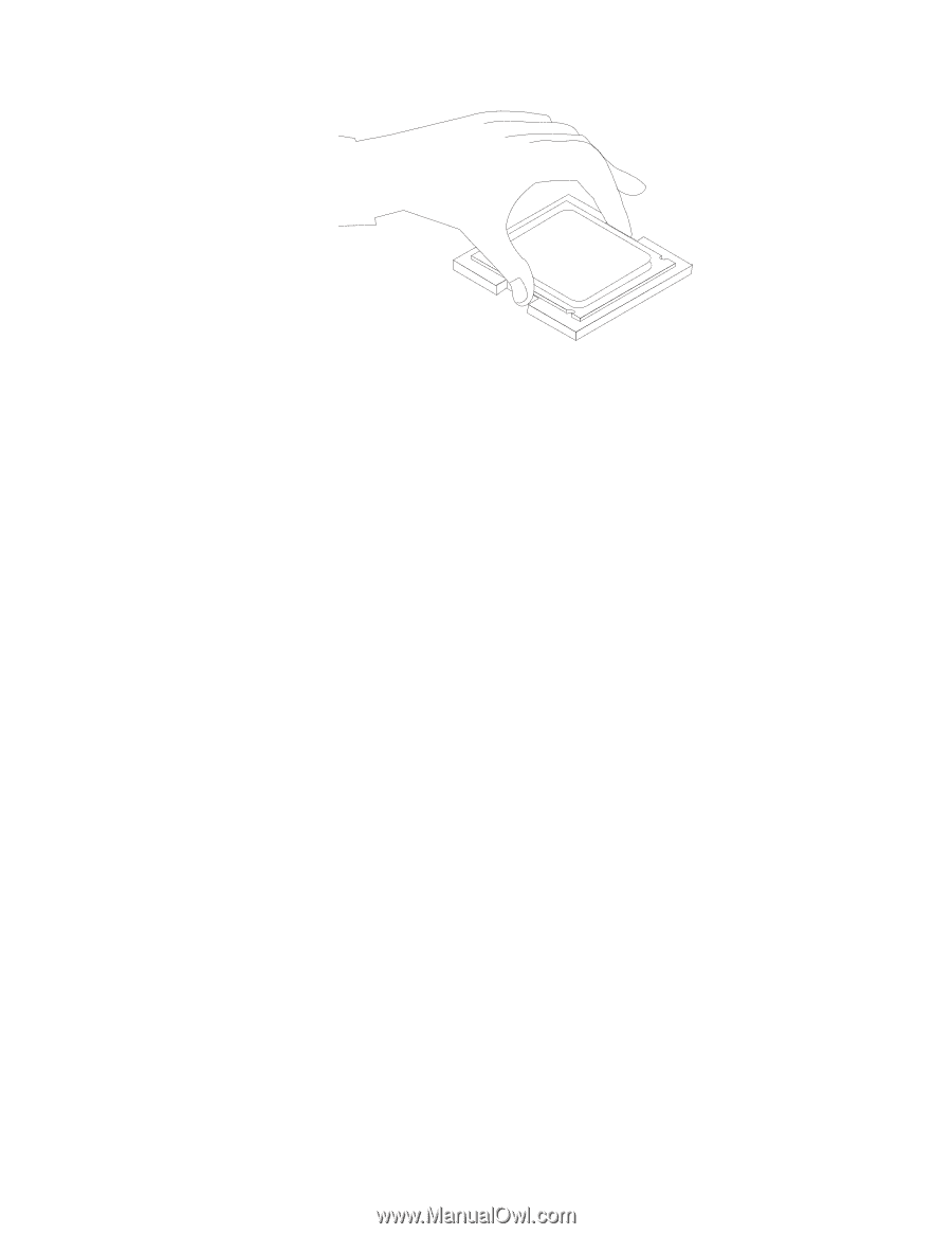
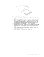
12. Lower the microprocessor retainer. 13. Lock the retainer with the small handle to secure the microprocessor in the socket. 14. The new retention bracket has plastic one-way rings on the posts that insert into the rear of the new system board. Install the new retention bracket by aligning the posts on the module with the holes in the system board and pushing the posts through the holes until the retention bracket is secure. 15. Install the heat sink and fan assembly on the new system board. 16. Install the new system board into the chassis and align the screw holes with those in the chassis. Insert and tighten the screws that secure the system board. 17. Connect all the cables to the system board. See "Identifying parts on the system board" on page 85. 18. Go to "Completing the FRU replacement" on page 107. Chapter 8. Replacing FRUs (Type 7848) 103
-
 1
1 -
2
-
3
-
4
-
5
-
6
-
7
-
8
-
9
-
10
-
11
-
12
-
13
-
14
-
15
-
16
-
17
-
18
-
19
-
20
-
21
-
22
-
23
-
24
-
25
-
26
-
27
-
28
-
29
-
30
-
31
-
32
-
33
-
34
-
35
-
36
-
37
-
38
-
39
-
40
-
41
-
42
-
43
-
44
-
45
-
46
-
47
-
48
-
49
-
50
-
51
-
52
-
53
-
54
-
55
-
56
-
57
-
58
-
59
-
60
-
61
-
62
-
63
-
64
-
65
-
66
-
67
-
68
-
69
-
70
-
71
-
72
-
73
-
74
-
75
-
76
-
77
-
78
-
79
-
80
-
81
-
82
-
83
-
84
-
85
-
86
-
87
-
88
-
89
-
90
-
91
-
92
-
93
-
94
-
95
-
96
-
97
-
98
-
99
-
100
-
101
-
102
-
103
-
 104
104 -
 105
105 -
 106
106 -
 107
107 -
 108
108 -
 109
109 -
 110
110 -
 111
111 -
 112
112 -
 113
113 -
 114
114 -
115
-
116
-
117
-
118
-
119
-
120
-
121
-
122
-
123
-
124
 |
 |