Lenovo ThinkCentre M62z Hardware Maintenance Manual (HMM) (July 2012) - ThinkC - Page 101
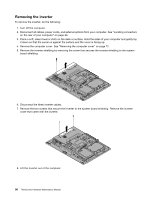
Replacing the inverter
 |
View all Lenovo ThinkCentre M62z manuals
Add to My Manuals
Save this manual to your list of manuals |
Page 101 highlights
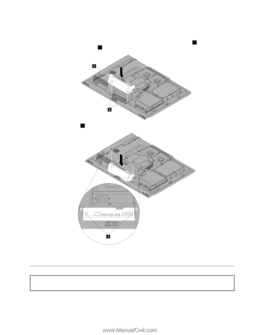
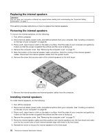
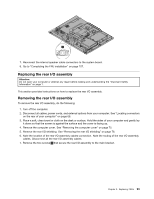
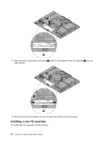
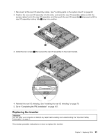
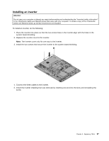
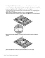
1. Reconnect all the rear I/O assembly cables. See "Locating parts on the system board" on page 69. 2. Position the new rear I/O assembly into the slots, and route the rear I/O assembly cables so that the excess cables tuck in the rear I/O assembly, and then push the rear I/O assembly 1 downward until the rear I/O assembly-locking tabs 2 snap into position. 3. Install the two screws 1 that secure the rear I/O assembly to the main bracket. 4. Reinstall the rear I/O shielding. See "Installing the rear I/O shielding" on page 76. 5. Go to "Completing the FRU installation" on page 107. Replacing the inverter Attention: Do not open your computer or attempt any repair before reading and understanding the "Important Safety Information" on page 1. This section provides instructions on how to replace the inverter. Chapter 9. Replacing FRUs 95
-
 1
1 -
2
-
3
-
4
-
5
-
6
-
7
-
8
-
9
-
10
-
11
-
12
-
13
-
14
-
15
-
16
-
17
-
18
-
19
-
20
-
21
-
22
-
23
-
24
-
25
-
26
-
27
-
28
-
29
-
30
-
31
-
32
-
33
-
34
-
35
-
36
-
37
-
38
-
39
-
40
-
41
-
42
-
43
-
44
-
45
-
46
-
47
-
48
-
49
-
50
-
51
-
52
-
53
-
54
-
55
-
56
-
57
-
58
-
59
-
60
-
61
-
62
-
63
-
64
-
65
-
66
-
67
-
68
-
69
-
70
-
71
-
72
-
73
-
74
-
75
-
76
-
77
-
78
-
79
-
80
-
81
-
82
-
83
-
84
-
85
-
86
-
87
-
88
-
89
-
90
-
91
-
92
-
93
-
94
-
95
-
 96
96 -
 97
97 -
 98
98 -
 99
99 -
 100
100 -
 101
101 -
 102
102 -
 103
103 -
 104
104 -
 105
105 -
 106
106 -
107
-
108
-
109
-
110
-
111
-
112
-
113
-
114
-
115
-
116
-
117
-
118
-
119
-
120
-
121
-
122
-
123
-
124
-
125
-
126
 |
 |