Lenovo ThinkCentre M62z Hardware Maintenance Manual (HMM) (July 2012) - ThinkC - Page 93
Removing the microprocessor and heat sink assembly, b. Partially remove screw
 |
View all Lenovo ThinkCentre M62z manuals
Add to My Manuals
Save this manual to your list of manuals |
Page 93 highlights
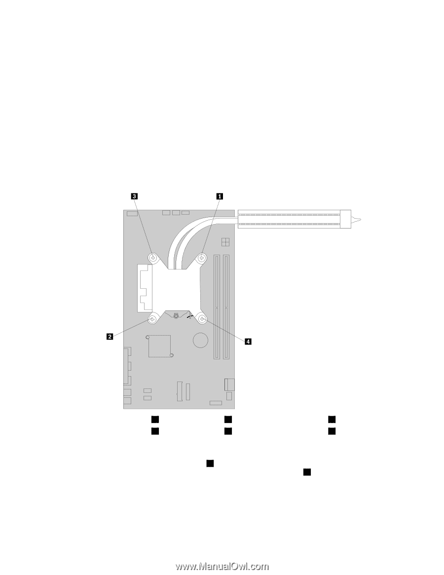
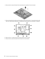
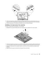
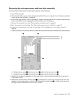
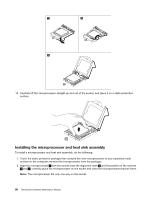
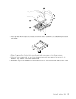
Removing the microprocessor and heat sink assembly To remove the microprocessor and heat sink assembly, do the following: 1. Turn off the computer. 2. Disconnect all cables, power cords, and external options from your computer. See "Locating connectors on the rear of your computer" on page 66. 3. Place a soft, clean towel or cloth on the desk or surface. Hold the sides of your computer and gently lay it down so that the screen is against the surface and the cover is facing up. 4. Remove the computer cover. See "Removing the computer cover" on page 72. 5. Open the system board shielding. See "Opening the system board shielding" on page 73. 6. Locate the microprocessor and heat sink assembly. See "Locating parts on the system board" on page 69. 7. Follow this sequence to remove the four screws that secure the heat sink assembly to the system board: a. Partially remove screw 1 , fully remove screw 2 , and then fully remove screw 1 . b. Partially remove screw 3 , fully remove screw 4 , and then fully remove screw 3 . 8. Carefully lift the heat sink assembly off the system board. Place the heat sink assembly on its side on a clean, flat surface. 9. Release the microprocessor retention latch 1 by pressing down on the end, moving it to the side, and releasing it to the open position. Open the microprocessor bracket frame 2 by lifting up the tab on the top edge. Keep the bracket frame in the open position. Chapter 9. Replacing FRUs 87
-
 1
1 -
2
-
3
-
4
-
5
-
6
-
7
-
8
-
9
-
10
-
11
-
12
-
13
-
14
-
15
-
16
-
17
-
18
-
19
-
20
-
21
-
22
-
23
-
24
-
25
-
26
-
27
-
28
-
29
-
30
-
31
-
32
-
33
-
34
-
35
-
36
-
37
-
38
-
39
-
40
-
41
-
42
-
43
-
44
-
45
-
46
-
47
-
48
-
49
-
50
-
51
-
52
-
53
-
54
-
55
-
56
-
57
-
58
-
59
-
60
-
61
-
62
-
63
-
64
-
65
-
66
-
67
-
68
-
69
-
70
-
71
-
72
-
73
-
74
-
75
-
76
-
77
-
78
-
79
-
80
-
81
-
82
-
83
-
84
-
85
-
86
-
87
-
 88
88 -
 89
89 -
 90
90 -
 91
91 -
 92
92 -
 93
93 -
 94
94 -
 95
95 -
 96
96 -
 97
97 -
 98
98 -
99
-
100
-
101
-
102
-
103
-
104
-
105
-
106
-
107
-
108
-
109
-
110
-
111
-
112
-
113
-
114
-
115
-
116
-
117
-
118
-
119
-
120
-
121
-
122
-
123
-
124
-
125
-
126
 |
 |