Lenovo ThinkCentre M62z Hardware Maintenance Manual (HMM) (July 2012) - ThinkC - Page 97
Installing a system board, system board
 |
View all Lenovo ThinkCentre M62z manuals
Add to My Manuals
Save this manual to your list of manuals |
Page 97 highlights
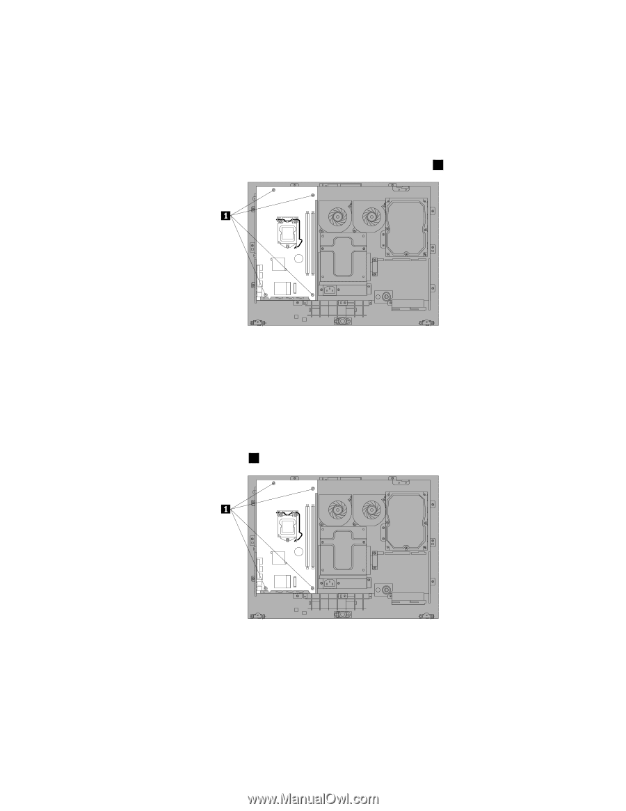
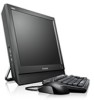
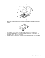
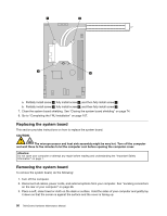
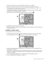
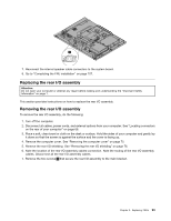
4. Remove the computer cover. See "Removing the computer cover" on page 72. 5. Open the system board shielding. See "Opening the system board shielding" on page 73. 6. Note the locations of all cable connections on the system board and disconnect all cables. See "Locating parts on the system board" on page 69. 7. Remove the microprocessor and heat sink assembly from the system board. See "Removing the microprocessor and heat sink assembly" on page 87. 8. Remove the four screws that attach the system board to the main bracket 1 . 9. Carefully lift the system board out of the chassis. 10. Remove the memory modules from the failing system board and install them in the same locations on the new system board. Installing a system board To install a system board, do the following: 1. Install the new system board into the chassis and align the screw holes with those in the chassis. 2. Insert and tighten the four screws 1 that secure the system board to the main bracket. 3. Reconnect all cables that were disconnected from the system board. See "Locating parts on the system board" on page 69. 4. Reinstall the microprocessor and heat sink assembly that were removed. Route the cables so that they will not be pinched by any FRUs and covers. See "Installing the microprocessor and heat sink assembly" on page 88. 5. Close the system board shielding. See "Closing the system board shielding" on page 74. 6. Go to "Completing the FRU installation" on page 107. Chapter 9. Replacing FRUs 91
-
 1
1 -
2
-
3
-
4
-
5
-
6
-
7
-
8
-
9
-
10
-
11
-
12
-
13
-
14
-
15
-
16
-
17
-
18
-
19
-
20
-
21
-
22
-
23
-
24
-
25
-
26
-
27
-
28
-
29
-
30
-
31
-
32
-
33
-
34
-
35
-
36
-
37
-
38
-
39
-
40
-
41
-
42
-
43
-
44
-
45
-
46
-
47
-
48
-
49
-
50
-
51
-
52
-
53
-
54
-
55
-
56
-
57
-
58
-
59
-
60
-
61
-
62
-
63
-
64
-
65
-
66
-
67
-
68
-
69
-
70
-
71
-
72
-
73
-
74
-
75
-
76
-
77
-
78
-
79
-
80
-
81
-
82
-
83
-
84
-
85
-
86
-
87
-
88
-
89
-
90
-
91
-
 92
92 -
 93
93 -
 94
94 -
 95
95 -
 96
96 -
 97
97 -
 98
98 -
 99
99 -
 100
100 -
 101
101 -
 102
102 -
103
-
104
-
105
-
106
-
107
-
108
-
109
-
110
-
111
-
112
-
113
-
114
-
115
-
116
-
117
-
118
-
119
-
120
-
121
-
122
-
123
-
124
-
125
-
126
 |
 |