LiftMaster SL595 SL595 Manual - Page 10
Post Mounting (sl585 And Sl595)
 |
View all LiftMaster SL595 manuals
Add to My Manuals
Save this manual to your list of manuals |
Page 10 highlights
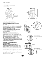
POST MOUNTING (SL585 AND SL595) RETRO-FIT INSTALLATION The operators come from the factory configured to mount to an inside the frame post mount dimension of 26" (66 cm) (outside to outside of posts). The frame comes slotted to accommodate posts 24-1/8" (61 cm) to 26" (66 cm), outside to outside (Figure 1). NOTE: If you are replacing a SL580, the frame will require adjustment to 24-1/8". Figure 1 NEW INSTALLATION (FIGURES 2 AND 3) 1. Locate and anchor two posts made of 3" (7.6 cm) outer diameter heavy walled pipe. Posts should be parallel and square to the gate. 2. Locate electrical conduit, as required, prior to pouring concrete. 3. Secure operator to posts using four 3" (7.6 cm) U-bolts and hardware provided. 26" (66 cm) Post to Post Adjustment 24-1/8" (61 cm) Figure 2 End Post Fence Line 8.5" (21.6 cm) Gate 6" (15.2 cm) 26" (66 cm) Outside To Outside 3" (7.6 cm) Outside Diameter Heavy Wall Fence Pipe 14" (35.6 cm) Min. Ground Level Depth As Required By Local Codes or Below Frost Line SL585 ONLY Figure 2 Drive and Idler Sprocket Toward Gate Side Angle Bracket 3" (7.6 cm) U-bolt (4 required) Power and Control Wiring Must Be Run In Separate Conduit Figure 3 End Post Fence Line 8.5" (21.6 cm) 6" (15.2 cm) Gate 24" (61 cm) Inside to inside 3" (7.6 cm) Outside Diameter Heavy Wall Fence Pipe 39" (99.1 cm) Min. Ground Level Depth As Required By Local Codes or Below Frost Line SL595 ONLY Figure 3 12" (30.5 cm) Minimum From Ground Power and Control Wiring Must Be Run In Separate Conduit SL595 ONLY 10 Drive and Idler Sprocket Toward Gate Side 3" (7.6 cm) U-bolt (4 required)
-
 1
1 -
2
-
3
-
4
-
 5
5 -
 6
6 -
 7
7 -
 8
8 -
 9
9 -
 10
10 -
 11
11 -
 12
12 -
 13
13 -
 14
14 -
 15
15 -
16
-
17
-
18
-
19
-
20
-
21
-
22
-
23
-
24
-
25
-
26
-
27
-
28
-
29
-
30
-
31
-
32
-
33
-
34
-
35
-
36
-
37
-
38
-
39
-
40
 |
 |
