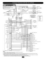
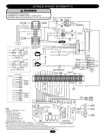
LiftMaster SL595 SL595 Manual - Page 25
CONTROL BOARD PROGRAMMING AND FEATURES (CONTINUED), On when Interrupt/Safety Loop activated
 |
View all LiftMaster SL595 manuals
Add to My Manuals
Save this manual to your list of manuals |
Page 25 highlights
CONTROL BOARD PROGRAMMING AND FEATURES (CONTINUED) FORCE CONTROL Set the force control pot such that the unit will complete a full cycle of gate travel but can be reversed off an obstruction without applying an unreasonable amount of force. On most operators this will be around the middle of the range. NOTE: For LED location refer to illustration on previous page. Force Control Max. Min. DIAGNOSTICS (LEDS AND CODES) There are three diagnostic LEDs. Two red LEDs (OLS, CLS) are indicators for the open and close limits. The LEDs are illuminated when the limit switch contacts are closed. The third amber LED (DIAG) is used to blink out diagnostic codes. The number is the count of the number of times the LED is on in an 8 second period. The LED is on for approximately 1/2 second and repeats every second until the number is reached. There will be a pause following each pulse cycle (1-6 pulses) to differentiate between the different diagnostic codes. LED Code Flashed OFF 1 2 3 4 5 6 On No Flash Diagnostic Meaning Cleared By Normal operation Single entrapment sensed Double entrapment Failed or no hall effect sensor Exceed maximum motor run time Limit fault Loss of communications between master and second during run mode Motor not learned N/A Control Input Hard Input* Removal of problem Hard Input* Control Input Removal of problem Completion of Motor Learn Routine *Hard inputs include open override, close override and stop inputs. RELAY DRIVE TROUBLESHOOTING LEDS There are 5 troubleshooting LEDs on relay drives K1 through K5. These LEDs will be illuminated when the microcontroller relay drive is activated. LED LED NAME DESCRIPTION D6 Contactor A D5 Contactor B D4 SAM D3 Lock D2 Alarm On when Contactor A is activated On when Contactor B is activated On when SAM relay is activated On when Mag Lock relay is activated On when Alarm Relay is activated TROUBLESHOOTING LEDS There are 9 troubleshooting LEDs. LED LED NAME D11 D13 D15 D17 (Green) D19 D21 D24 D29 Radio Shadow Hard Close Stop Soft Open Hard Open Interrupt (Safety) Loop Obstruction Open D31 Obstruction Close DESCRIPTION On when Radio switch is activated On when Shadow Loop is activated On when Close switch is activated On when Stop switch is not activated On when Open switch is activated On when Open switch is activated On when Interrupt/Safety Loop activated On when Edge is activated or when Photo Eye Beam is broken On when Edge is activated or when Photo Eye Beam is broken 25
-
 1
1 -
2
-
3
-
4
-
5
-
6
-
7
-
8
-
9
-
10
-
11
-
12
-
13
-
14
-
15
-
16
-
17
-
18
-
19
-
 20
20 -
 21
21 -
 22
22 -
 23
23 -
 24
24 -
 25
25 -
 26
26 -
 27
27 -
 28
28 -
 29
29 -
 30
30 -
31
-
32
-
33
-
34
-
35
-
36
-
37
-
38
-
39
-
40
 |
 |
