LiftMaster SL595 SL595 Manual - Page 11
Install Gate Bracket And Drive Chain - gate operator manual
 |
View all LiftMaster SL595 manuals
Add to My Manuals
Save this manual to your list of manuals |
Page 11 highlights
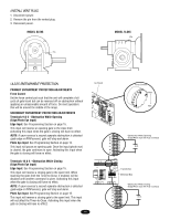
INSTALL GATE BRACWKEAT ARNDNDIRNIVGE CHAIN CAUTION To prevent damage to the operator or gate, DO NOT drive the limit (nuts) actuators on the shaft past their normal positions. Figure 1 WARNING Gate "Outside" "Inside" WARNING 1. Mount gate brackets to the vertical front and rear posts of the gate (Figure 1). 2. Remove the operator cover or open access door. 2" (5.1 cm) U-bolts With Lock Washers AVERTISSEMENT 3. Locate and engage the manual disconnect and lock it in place (refer to page 12). and Nuts 4. Connect chain take-up bolt to the end of the chain and attach to the rear gate bracket (Figure 2). Gate Bracket AVERTISSEMENT 5. Ensure that the drive and idler sprockets are in line with each other. Thread the chain through the plastic chain guide, around drive and idler sprockets, and then through the second plastic Figure 2 ATTENTION chain guide toward front gate bracket (Figure 3). 6. Adjust the chain to proper length and attach second take-up bolt to chain end. Secure the take-up bolt to the front gate bracket as shown. AVERTISSEMENT Adjust nuts on chain take-up bolts to remove chain slack. A general rule of thumb is to leave a maximum of 1" (2.5 cm) of chain slack for every 10' (3.1 m) of chain length. Do not overtighten chain. Anti-Rotation Set Screw NOTE ABOUT SOME TYPES OF CANTILEVER GATES: With some cantilever gates over 20' (6.1 m) long, you may need to add a brace along the length of the gate to prevent the gate from bowing when chain is tightened. This may also be required on some styles of gates that are constructed out of aluminum. If positioned properly, this brace can also be used as a chain support. ADVERTENCIA * * * Gate Brackets Must Be Level and Centered ADVERTENCIA With Bottom of Idler Sprocket. PRECAUCIÓN Figure 3 Gate Bracket Drive Sprocket Gate Post ADVERTENCIA Idler Sprocket Idler Sprocket Insert Chain Through Plastic Guides Safety Bracket 11
-
 1
1 -
2
-
3
-
4
-
5
-
 6
6 -
 7
7 -
 8
8 -
 9
9 -
 10
10 -
 11
11 -
 12
12 -
 13
13 -
 14
14 -
 15
15 -
 16
16 -
17
-
18
-
19
-
20
-
21
-
22
-
23
-
24
-
25
-
26
-
27
-
28
-
29
-
30
-
31
-
32
-
33
-
34
-
35
-
36
-
37
-
38
-
39
-
40
 |
 |
