LiftMaster SL595 SL595 Manual - Page 19
TO ERASE ALL REMOTE CONTROL CODES, Terminals 6 & 5 Com - Soft Open - parts
 |
View all LiftMaster SL595 manuals
Add to My Manuals
Save this manual to your list of manuals |
Page 19 highlights
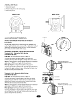
M HIGH NORM M PROGRAMMING THE REMOTE TO THE RECEIVER 1. Pry open the front panel of receiver case with a coin or a screwdriver. Re-connect power to operator (Figure 3). 2. Press and release the "learn" button on the receiver. The learn indicator light will glow steadily for 30 seconds. 3. Within 30 seconds, press and hold the button on the hand-held remote that you wish to operate your gate operator. The opener will now operate when the push button on either the receiver or the remote control is pressed. Repeat Steps 2 and 3 for each remote control that will be used to operate the gate operator. TO ERASE ALL REMOTE CONTROL CODES Press and hold the "learn" button on the receiver panel until the indicator light turns off (about 6 seconds). All remote codes are now erased. Then follow the steps above to reprogram each remote control. Figure 2 CONSTANT Jumper OPERATION Output Duration Terminals MOMENTARY Jumper OPERATION Output Duration Terminals Figure 3 OPENING RECEIVER OPEN RECEIVER Connect Antenna Indicator Light Learn Button C P2 M 24V 12V Output Duration Terminals Security Mode Power Supply Jumper NOTICE: To comply with FCC and or Industry Canada (IC) rules, adjustment or modifications of this receiver and/or remote control are prohibited, except for changing the code setting or replacing the battery. THERE ARE NO OTHER USER SERVICEABLE PARTS. Tested to Comply with FCC Standards FOR HOME OR OFFICE USE. Operation is subject to the following two conditions: (1) this device may not cause harmful interference, and (2) this device must accept any interference received, including interference that may cause undesired operation. ACCESSORY WIRING REMOTELY MOUNTED STOP/RESET CONTROL WIRING • This control will function as a Stop/Reset command and is to be wired within line of sight of the gate. • Wire Stop/Reset control station to terminals 3 and 5 on the control box on the operator. Make sure that all Stop/Reset controls are wired in series. Terminals 6 & 5 (Com) - Soft Open These terminals are intended for use as a general open control. Accessories that may be wired to this input include: Telephone Entry Systems, Radio Receiver (Commercial Applications), Exit Loop Detector, Keypads, 7-Day Timer. NOTE: Will not override a double entrapment (signalled by the gate stopped and entrapment alarm on). Control Conduit Control Conduit 1 234 567 12 3 Stop/Reset Button Stop/Reset Button 1 2 3 4 5 6 7 8 9 10 11 12 13 14 123 56 789 0# Soft Open 19
-
 1
1 -
2
-
3
-
4
-
5
-
6
-
7
-
8
-
9
-
10
-
11
-
12
-
13
-
 14
14 -
 15
15 -
 16
16 -
 17
17 -
 18
18 -
 19
19 -
 20
20 -
 21
21 -
 22
22 -
 23
23 -
 24
24 -
25
-
26
-
27
-
28
-
29
-
30
-
31
-
32
-
33
-
34
-
35
-
36
-
37
-
38
-
39
-
40
 |
 |
