LiftMaster SL595 SL595 Manual - Page 30
Single Phase Schematic - 2 hp
 |
View all LiftMaster SL595 manuals
Add to My Manuals
Save this manual to your list of manuals |
Page 30 highlights
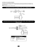
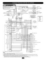
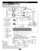
SINGLE PHASE SCHEMATIC W A R N I N G To protect against fire and electrocution: • DISCONNECT power BEFORE installing or servicing operator. • Replace ONLY with fuse of same type and rating. Fuse: 3AG, 3.2A, 120V, SLO-BLO A1 A2 13 14 5 6 3 4 1 2 (TB2) L1 POWER IN L2 SEE NOTE 1 115V. BRAKE SOLENOID GY 1 3 BL-BK BK BL 8 OL Y 5 BK PU 42 BL-BK 115V. CONNECTION GY 1 BL-BK BL Y PU 8 OL BK 5 23 4 BK BL-BK 208/230V. CONNECTION 230V. BRAKE SOLENOID LOOP WIRING (See NOTE 7) R4 TB1-5 TB2-CD TB2-AB TB1-20 TB1-19 4 6 FREE EXIT 7 LOOP 8 HARNESS 9 (10 PIN) 10 Y/BK GRAY RED BLACK A1 A2 13 14 5 6 3 4 1 2 CONTACTOR A & B 208/230V SHOWN SEE NOTE 6 L/S "AC"NC YEL/BLK L/S "BC"NC SHADOW CLOSE STOP OVERLOAD G J2 PLUG ON PCB RPM BOARD BLACK RED WHITE 11 10 9 ORANGE 8 PURPLE 7 6 1 GROUND GREEN 5 4 3 CONTACTOR A A1 ORANGE 2 1 CONTACTOR B A1 PURPLE 2 RADIO TERMINAL BLOCK OR P Y/BK SOFT OPEN TB1-15 BLUE ALARM BLACK Y/BK FIELD CONNECTIONS TB1-3 Y/BK TB1-6 BROWN 4 GREEN (SEE NOTE 7) OPEN CLOSE MASTER EDGE/PHOTO SECOND EYE 24 VAC ACCESSORY POWER MAGLOCK INTERRUPT LOOP EXIT LOOP R1 R2 24 VAC R3 R4 RADIO SIGNAL FACTORY INSTALLED RADIO INTERRUPT HARD OPEN VDC COM RADIO 1 2 3 4 5 6 7 8 9 10 11 12 13 14 15 16 17 18 19 20 BLACK BLUE R1 BLUE OR/BLK WHITE GREEN ORANGE BROWN GREEN STOP RESET PUR/WHT PURPLE TB1-8 TB1-3 TB2-CD TB2-AB TB1-18 TB1-17 4 6 INTERRUPT 7 LOOP 8 HARNESS 9 (10 PIN) 10 J1 1 2 3 4 5 6 7 8 9 10 11 12 13 14 15 16 J4 1 2 J2 NOTES: 1. Voltage: 115, 208 & 230 volt - 1 phase. 2. Horsepower 1/2 & 1 HP. 3. Transformer primary voltage is The same as the operator voltage. Secondary 24v/60va. For reference primary wire colors: 120v black, 208v red, 230v orange, 460v purple, 575v grey. 4. Terminal designations shown for 115v. 5. Terminal block in limit switch enclosure (SL595 only). 6. For single phase 115v operation, there is an additional white wire from contactor (GL CONTROL BOARD) A2 to contactor B4 and the black wire from the transformer to contactor B4 goes to B6. 7. When using a remote control or single button control station in lieu of the soft open feature, perform the following modific ations to the operator: • Remove the green wire from R4 of the radio block and mount the wire to terminal block TB1 position 6. • Move the brown wire on terminal block TB1 position 6 (from radio block R4) to terminal block TB1 position 1. 30 R2 BK RD OPEN Y/BK OR CLOSE Y/BK GRN STOP Y/BK Y/BK Y/BK RESET
-
 1
1 -
2
-
3
-
4
-
5
-
6
-
7
-
8
-
9
-
10
-
11
-
12
-
13
-
14
-
15
-
16
-
17
-
18
-
19
-
20
-
21
-
22
-
23
-
24
-
 25
25 -
 26
26 -
 27
27 -
 28
28 -
 29
29 -
 30
30 -
 31
31 -
 32
32 -
 33
33 -
 34
34 -
 35
35 -
36
-
37
-
38
-
39
-
40
 |
 |
