LiftMaster SL595 SL595 Manual - Page 9
Installation, Pad Mounting (sl585 Only) - gate operator
 |
View all LiftMaster SL595 manuals
Add to My Manuals
Save this manual to your list of manuals |
Page 9 highlights
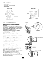
INSTALLATION PAD MOUNTING (SL585 ONLY) Figure 1 RETRO-FIT INSTALLATION The operator is shipped from the factory with the lower mounting angles configured out (Figure 1). If you have pad constrictions, either angle can be unbolted and reversed to angle in. NOTE: If you are replacing an SL580 and wish to use the same pad mounting hardware, the gate side mounting angle must be installed angle in. NEW INSTALLATION Concrete Pad Preparation 1. Lay out concrete pad (Figure 2). 2. Locate electrical conduit, as required, prior to pouring concrete. 3. Pour concrete pad. 4. Secure operator (Figure 3) to the concrete pad using four 1/2" concrete anchors (not provided). Figure 2 4" (10.2 cm) 10-7/8" (27.6 cm) Fence Line Angle Out Angle In Rear of Gate or Back Frame 1" (2.5 cm) 18" (45.7 cm) 7" (17.8 cm) 21-1/8" (53.7 cm) 36" (91.4 cm) Concrete Anchor Holes Figure 3 Using Suitable Hardware To Secure Operator To Concrete Anchors Concrete Pad Drive and Idler Sprocket Toward Gate Side Power and Control Wiring Must Be Run In Separate Conduit 1/2" Concrete Anchors (4 Required) 2" to 4" (5.1 to 10.2 cm) Above Grade Depth Required By Local Codes or Below Frost Line 9
-
 1
1 -
2
-
3
-
 4
4 -
 5
5 -
 6
6 -
 7
7 -
 8
8 -
 9
9 -
 10
10 -
 11
11 -
 12
12 -
 13
13 -
 14
14 -
15
-
16
-
17
-
18
-
19
-
20
-
21
-
22
-
23
-
24
-
25
-
26
-
27
-
28
-
29
-
30
-
31
-
32
-
33
-
34
-
35
-
36
-
37
-
38
-
39
-
40
 |
 |
