LiftMaster SL595 SL595 Manual - Page 27
Troubleshooting, Power Up And Does
 |
View all LiftMaster SL595 manuals
Add to My Manuals
Save this manual to your list of manuals |
Page 27 highlights
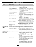
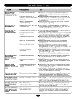
TROUBLESHOOTING FAULT POSSIBLE CAUSE FIX MASTER OR SECOND OPERATOR IS NOT FUNCTIONING PROPERLY 1) Failure to cycle power after setup 2) Communication wiring may be damaged or improperly wired for dual gate operation 3) Master or second unit is not programmed correctly ➤ The power to each unit must be cycled in order to initiate proper master/second communication if the operators were previously in stand-alone mode. ➤ Make sure that the communication wire that is used is twisted pair and not run in the same conduit with any power wiring. Failure to do so will result in interference across the master/second communication line. ➤ Review program settings page 20 and check both the master and second for proper programming. OPERATOR RUNS IN WRONG DIRECTION 1) Operator's main power is out of phase ➤ Turn off the unit's main power at the breaker and swap any two (three phases only) power leads at the operator's main power switch. Apply power and retest the operator. See important note on page 12. OPERATOR RUNS BUT THEN STOPS AND REVERSES DIRECTION 1) Entrapment (force pot) incorrectly set 2) Gate is binding or not running smoothly 3) Clutch is not adjusted properly 4) Brake is not functioning properly 5) Observe red LEDs D29 and D31 6) RPM (Hall Effect) Sensor is not aligned ➤ This pot must be set so that the gate will run smoothly normally and reverse when encountering an obstruction. ➤ Disengage the manual release and roll gate open and close by hand at normal operating speed. Make sure that the gate runs smoothly and does not bind. If the gate is hard to move or binds, repair the gate. ➤ Adjust the clutch so that the operator can move the gate throughout its travel without slipping but will slip when the gate hits an obstruction. ➤ Make sure that the brake operates correctly. The brake should disengage when the contactor activates and engage when the contactor releases. ➤ Both LEDs will indicate the activation of entrapment protection devices on terminals TB1-9 and TB1-10 on the control board. Remove the devices and retest. If the operator now runs without fault, check those accessories as well as their wiring. ➤ Make sure that the sensor is adjusted so that it is centered over the limit shaft's magnet and is 10-15 thousandths of and inch (business card thickness) from the magnet. ➤ Replace the sensor if it is adjusted correctly but continues to fail. MOTOR RUNS BUT GATE DOES NOT MOVE; OPERATOR STOPS AND ALARMS 1) Clutch is not adjusted properly 2) Operator's manual release is not aligned ➤ Adjust the clutch so that the operator can move the gate throughout its travel without slipping but will slip when the gate hits an obstruction. ➤ Make sure that the manual release is not engaged. The operator's manual release, when engaged, will set off the entrapment if the gate is given a command to move. OPERATOR OPENS 1) Active or malfunctioning accessory IMMEDIATELY UPON check the red input status LEDs, POWER UP AND DOES NOT D11-D13 CLOSE ➤ If any red LEDs are on, check the corresponding input. An installed accessory may be wired incorrectly or malfunctioning. Remove the accessory and test the operator. ➤ If the soft open or interrupt (safety) loop LED is on, make sure factory plug-in loop detectors are working properly and appropriate loops are installed on the loop input terminals. OPERATOR HAS TROUBLE 1) Operator's manual release is engaged LEARNING THE MOTOR ➤ Make sure the manual release is not engaged. The operator's manual release, when engaged, will not allow the entrapment sensor to provide feedback to the control board when the operator is moving. PROGRAMMING CHANGES 1) Check the save switch on switch S1-1 ➤ If the switch S1-1 is in the on position, any subsequent programming DO NOT EFFECT THE GATE changes will not affect the gate. To make programming changes, switch S1-1 off, make desired changes, and then switch S1-1 on. GATE EDGE PAUSES GATE 1) Open obstruction input is WHEN STRUCK DURING programmed incorrectly OPENING ➤ The open obstruction input has been programmed to function with photo eyes, not gate edges. Refer to page 15 and reprogram the obstruction inputs for correct operation. GATE DOES NOT ACTIVATE TIMER-TO-CLOSE AFTER THE CLOSE PHOTO EYE IS BROKEN 1) Close obstruction input is programmed incorrectly ➤ The close obstruction input has been programmed to function with gate edges, not photo eyes. Refer to page 15 and reprogram the obstruction inputs to match the accessories that are installed on operator. 27
-
 1
1 -
2
-
3
-
4
-
5
-
6
-
7
-
8
-
9
-
10
-
11
-
12
-
13
-
14
-
15
-
16
-
17
-
18
-
19
-
20
-
21
-
 22
22 -
 23
23 -
 24
24 -
 25
25 -
 26
26 -
 27
27 -
 28
28 -
 29
29 -
 30
30 -
 31
31 -
 32
32 -
33
-
34
-
35
-
36
-
37
-
38
-
39
-
40
 |
 |
