LiftMaster SL595 SL595 Manual - Page 28
Self-regulating Heater Accessory, Heater Wiring Diagram For 115v Operators
 |
View all LiftMaster SL595 manuals
Add to My Manuals
Save this manual to your list of manuals |
Page 28 highlights
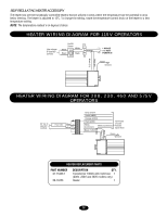
SELF-REGULATING HEATER ACCESSORY The heater kits are thermostatically controlled heaters that are utilized in areas where the temperature has the potential to drop below freezing. The heater is adjusted to 15˚C. To change the setting, rotate the temperature control knob on the heater to a new temperature setting. NOTE: The temperature readout is in degrees Celsius. HEATER WIRING DIAGRAM FOR 115V OPERATORS Line voltage to operator controls On/Off Switch White ON White Black Black OFF L1 1 PHASE L2 115 VOLT POWER IN Green Ground Black (N) Black (T1) HEATER WIRING DIAGRAM FOR 208, 230, 460 AND 575V OPERATORS 24 Vac to operator controls FusFibuslee d3e.2A3.2A Blue Yellow Grey (575V) Violet (480V) Orange (230V) Red (208V) White (Common) White (Common) Black (120V) Terminate unused transfer input wires Green Ground Black (N) Black (T1) HEATER REPLACEMENT PARTS PART NUMBER 21-15453-1 50-18423 DESCRIPTION QTY. Transformer 100VA with 3.2A fuse 1 (208V, 230V and 460V models only) Heater 1 28
-
 1
1 -
2
-
3
-
4
-
5
-
6
-
7
-
8
-
9
-
10
-
11
-
12
-
13
-
14
-
15
-
16
-
17
-
18
-
19
-
20
-
21
-
22
-
 23
23 -
 24
24 -
 25
25 -
 26
26 -
 27
27 -
 28
28 -
 29
29 -
 30
30 -
 31
31 -
 32
32 -
 33
33 -
34
-
35
-
36
-
37
-
38
-
39
-
40
 |
 |
